
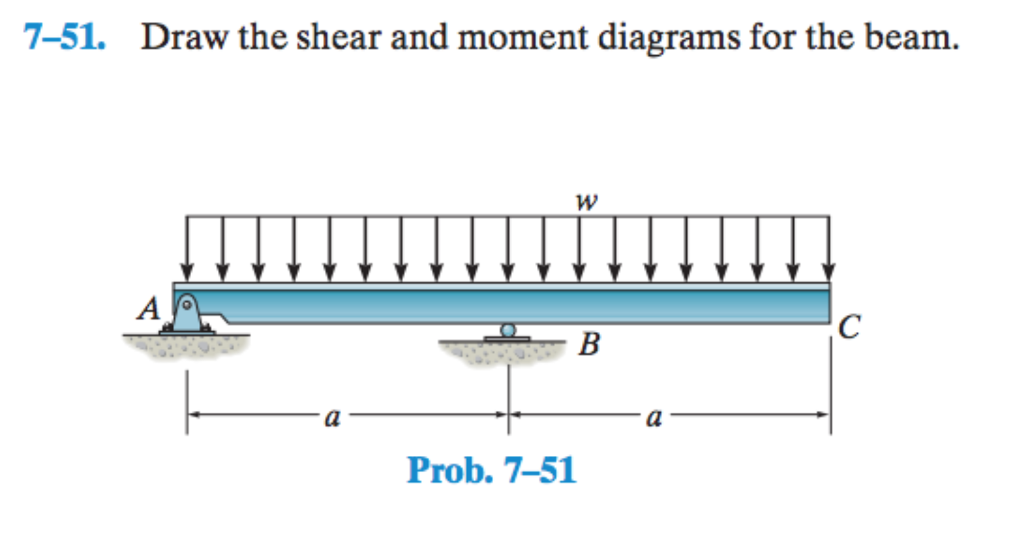
7-51 Draw The Shear And Moment Diagrams For The Beam
7-51 Draw The Shear And Moment Diagrams For The Beam - Draw the shear and moment diagrams for the beam. W a с b 를 l prob. Draw a free body diagram showing and labeling all load forces and support (reaction) forces, as well as any. B) set p = 30 kn, a = 2m, b = 4m. Web this is an example problem that will show you how to graphically draw a shear and moment diagram for a beam.
They are computed by applying the conditions of. In the questions the location x proceeds from left to right! Ft b 10 ft 20 ft 10 ft prob. We go through breaking a beam into segments, and then we learn about the relationships between shear force and moment. Calculate the reactions using the equilibrium equations (may not need to do this if choosing a cantilever beam and using the free side for the fbd). Web the first step in calculating these quantities and their spatial variation consists of constructing shear and bending moment diagrams, \(v(x)\) and \(m(x)\), which are the internal shearing forces and bending moments induced in the beam, plotted along the beam's length. V = shear force, lbs.

Drawing Shear and Moment Diagrams for Beam YouTube
Also, draw shear and moment diagrams, specifying values at all change of loading positions and at. Web this is an example problem that will show you how to graphically draw a shear and moment diagram for a beam. Draw the shear and moment diagrams for the beam. Web expert answer step 1 solution: Shear force.

Learn How To Draw Shear Force And Bending Moment Diagrams Engineering
Calculate the reactions using the equilibrium equations (may not need to do this if choosing a cantilever beam and using the free side for the fbd). Web learn to draw shear force and moment diagrams using 2 methods, step by step. V1 = 13,000 lb, v2. W = load per unit length, lbs./in. One of.
Solved 751. Draw the shear and moment diagrams for the
We go through breaking a beam into segments, and then we learn about the relationships between shear force and moment. View the full answer step 2 step 3 final answer previous question next question transcribed image text: Web 7.51 draw the shear and moment diagrams for the beam? V = shear force, lbs. T 777.

Learn How To Draw Shear Force And Bending Moment Diagrams Engineering
Draw the shear and moment diagrams for the beam. Web write shear and moment equations for the beams in the following problems. Web expert answer step 1 solution: W = load per unit length, lbs./in. Unfortunately it’s probably the one structural analysis skill most students struggle with most. We go through breaking a beam into.

Shear And Moment Diagrams For Beams
Unfortunately it’s probably the one structural analysis skill most students struggle with most. Web the first step in calculating these quantities and their spatial variation consists of constructing shear and bending moment diagrams, \(v(x)\) and \(m(x)\), which are the internal shearing forces and bending moments induced in the beam, plotted along the beam's length. P7.51.

Solved Draw the shear and moment diagrams for the beam, and
Web step 1 | draw a free body diagram. You'll get a detailed solution from a subject matter expert that helps you learn core concepts. Moment = 0 at point b: One of the ways to do this is through the use of shear and moment diagrams. V = shear force, lbs. Draw the shear.
Solved Draw the shear diagram for the beam. Follow
Web this is an example problem that will show you how to graphically draw a shear and moment diagram for a beam. Web for example, if w(x) is uniform, v(x) will be linear. Also, draw shear and moment diagrams, specifying values at all change of loading positions and at. Ft b 10 ft 20 ft.

Draw the shear and moment diagrams for the beam.
The final shear and moment diagrams for the beam are as follows: Web draw the shear force and bending moment diagrams for the beam shown in the figure, when dimensions and loadings of the beam get values a=1.0 m,b=1 m,c=3.2 m,d=0.8 m,f=16 kn,p=12 kn and q=23kn//m. Web for example, if w(x) is uniform, v(x) will.

Solved Draw the shear and moment diagrams for the beam.
Web draw the shear force and bending moment diagrams for the beam shown in the figure, when dimensions and loadings of the beam get values a=1.0 m,b=1 m,c=3.2 m,d=0.8 m,f=16 kn,p=12 kn and q=23kn//m. Web the first step in calculating these quantities and their spatial variation consists of constructing shear and bending moment diagrams, \(v(x)\).

Learn How To Draw Shear Force And Bending Moment Diagrams Engineering
Web this is an example problem that will show you how to graphically draw a shear and moment diagram for a beam. T 777 draw the shear and moment diagrams for the beam. To correctly determine the shear forces and bending moments along a beam we need to know all of the loads acting on.
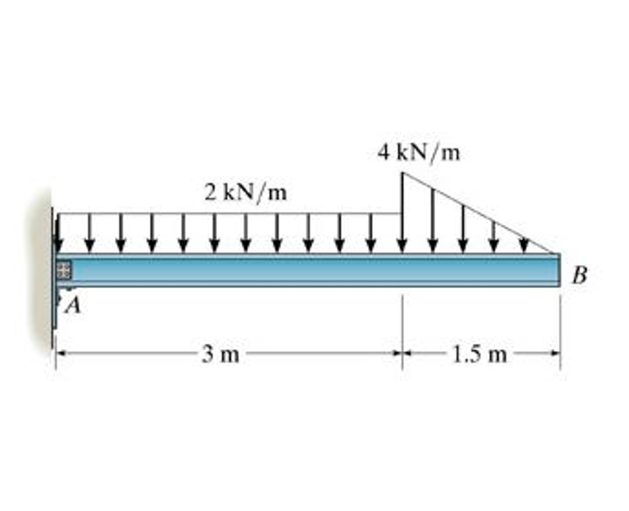
7-51 Draw The Shear And Moment Diagrams For The Beam This problem has been solved! Shear and moment diagrams are graphical representations of the variation of shear force and bending moment along the length of a structural element such as a beam. 3kn/m 10kn 6m b resultant moment about point a: The vertical support reaction at a on. Draw a free body diagram showing and labeling all load forces and support (reaction) forces, as well as any.
20 Kn 40 Kn/M Cl 150 Kn M 8 M 3 M Prob.
Web learn to draw shear force and moment diagrams using 2 methods, step by step. Web the first step in calculating these quantities and their spatial variation consists of constructing shear and bending moment diagrams, \(v(x)\) and \(m(x)\), which are the internal shearing forces and bending moments induced in the beam, plotted along the beam's length. Web draw the shear force and bending moment diagrams for the cantilever beam supporting a concentrated load of 5 lb at the free end 3 ft from the wall. Web 7.51 draw the shear and moment diagrams for the beam?
By Drawing The Free Body Diagram You Identify All Of These Loads And Show Then On A Sketch.
Calculate the reactions using the equilibrium equations (may not need to do this if choosing a cantilever beam and using the free side for the fbd). Web this is an example problem that will show you how to graphically draw a shear and moment diagram for a beam. You'll get a detailed solution from a subject matter expert that helps you learn core concepts. Shear and moment diagrams are graphical representations of the variation of shear force and bending moment along the length of a structural element such as a beam.
Draw The Shear And Moment Diagrams For The Beam.
Web draw the shear force and bending moment diagrams for the beam shown in the figure, when dimensions and loadings of the beam get values a=1.0 m,b=1 m,c=3.2 m,d=0.8 m,f=16 kn,p=12 kn and q=23kn//m. View the full answer step 2 step 3 final answer previous question next question transcribed image text: Web to design a beam, it is essential to determine the maximum shear and moment in the structure. Web step 1 | draw a free body diagram.
Shear Force And Bending Moment Diagrams For Our Loaded Beam.
You'll get a detailed solution from a subject matter expert that helps you learn core concepts. In each problem, let x be the distance measured from left end of the beam. = deflection or deformation, in. Draw a free body diagram showing and labeling all load forces and support (reaction) forces, as well as any.