
A Section Line On A Drawing Shows The North Orientation
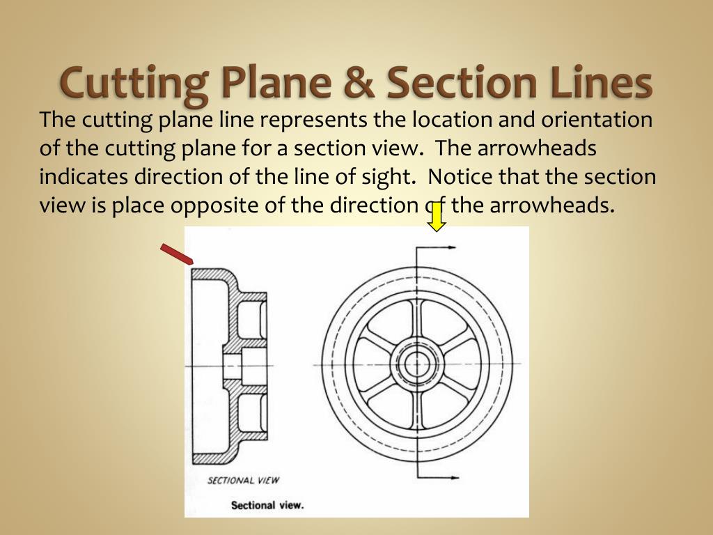
A Section Line On A Drawing Shows The North Orientation - The line that indicates the plane where the cut is made is called the section line. The location of the section on the plan. Study with quizlet and memorize flashcards containing terms like sectional view,. A section, take a slice through the building or room and show the relationship between floors, ceilings. All the visible edges behind the.
By default, the section line height as high as the model. Layout drawings (plan view) should be drawn so that the direction of flow is from left to right or bottom to top of the sheet. Structure contour construction on the map in fig. For most purposes, the general use symbol of cast iron is used. The location of the section on the plan. A section, take a slice through the building or room and show the relationship between floors, ceilings. Web terms in this set (53) a section line on a drawing shows.

Plan, Section, Elevation Architectural Drawings Explained · Fontan
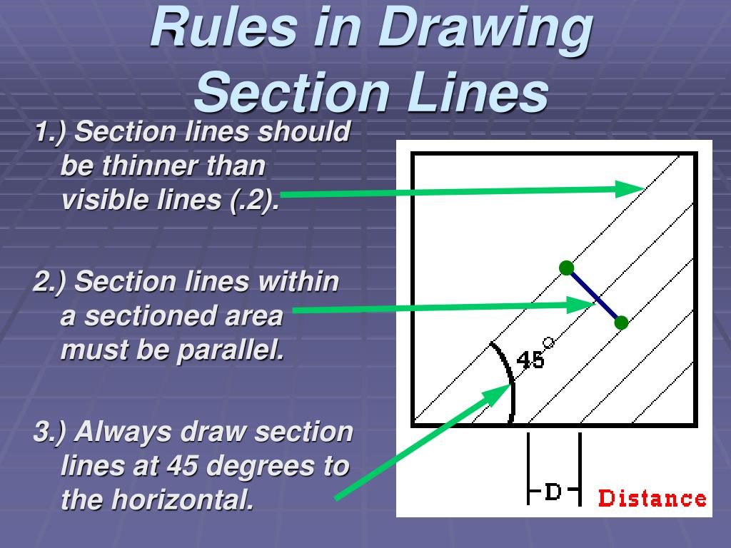
A section line on a drawing is used to indicate where a cut has been made through an object or building. Web section lines, or hatching, that represent the cut surface usually consist of thin parallel lines, as shown below, drawn at an angle of approximately 45° to the principal edges or axes of the.
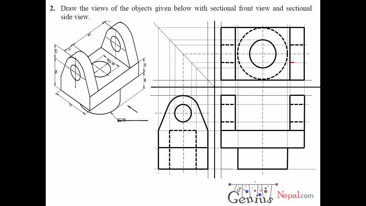
Engineering Drawing Tutorials / Orthographic Drawing with Sectional
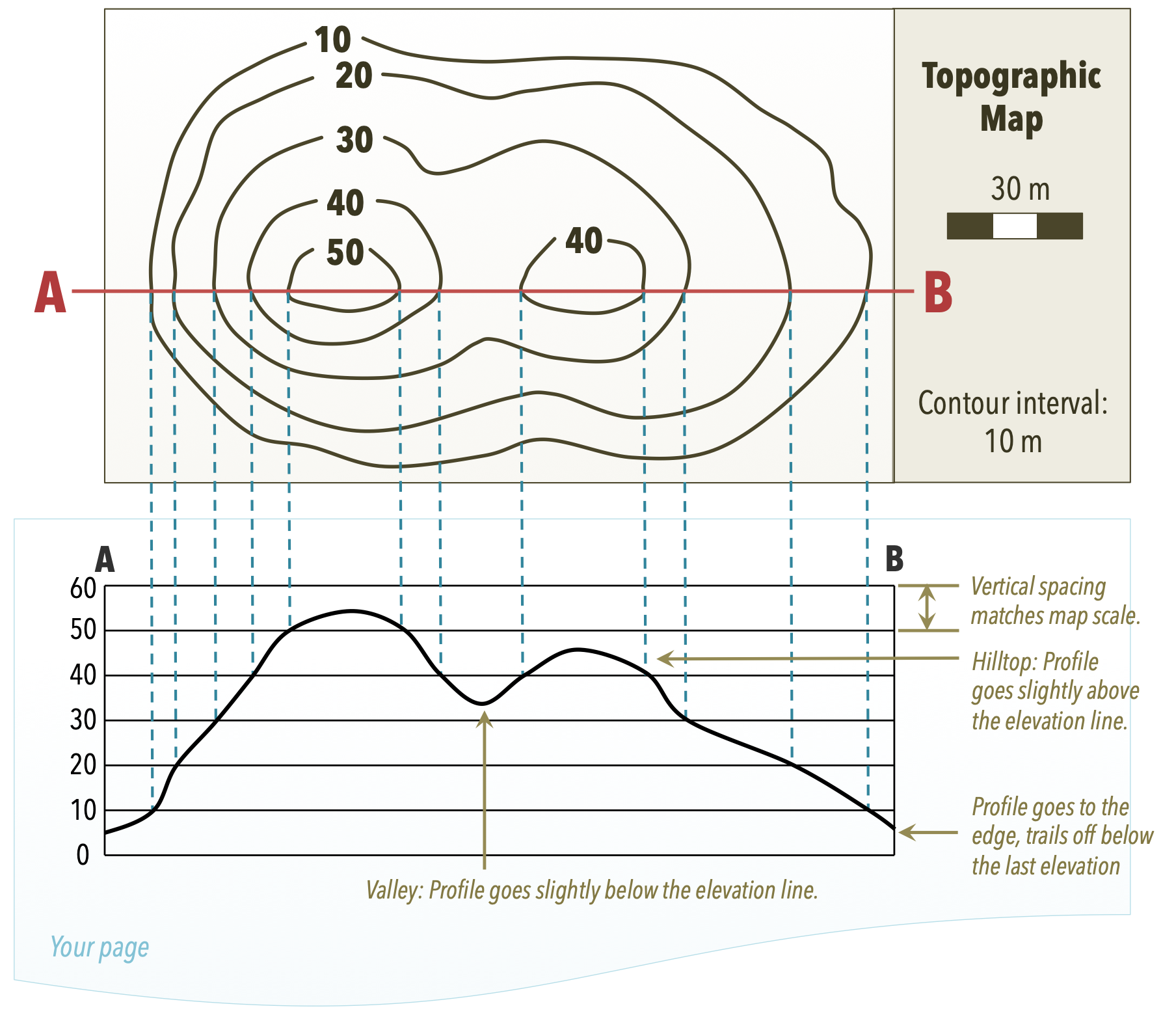
Layout drawings (plan view) should be drawn so that the direction of flow is from left to right or bottom to top of the sheet. Web with all respect, adding north arrow in floor plans is not helping anyone in any way. Web topographic map, showing technique for drawing a topographic profile along line ab..
PPT Introduction to Sketching Section Views PowerPoint Presentation
The location of the section on the plan is shown as xb. You may remember the technique for drawing a topographic profile from your introductory geology course (fig. Web a section line on a drawing shows the location of the section on the plan on electrical drawings, a solid line with a solid circle at.
AutoCAD Tutorials Introduction to Section or Sectional Views in AutoCAD
When planning receptacle placement in that section, consider the practicality and safety of access and usage. Section lines are bidirectional and you can specify the length and depth of the section line either visually, using the pointing device, or by entering numeric values. Web section cut indicators identifies the plane where, how and on which.
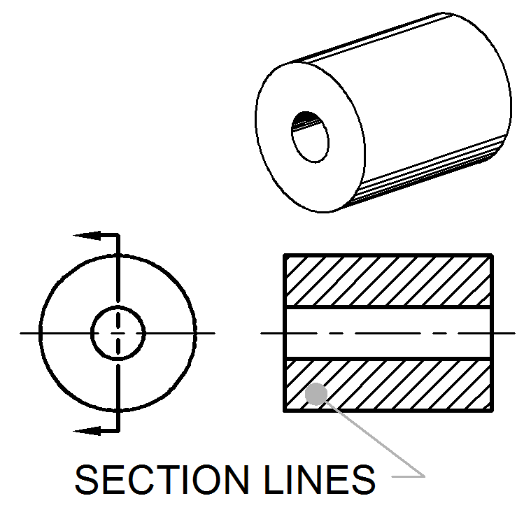
Section Lines ToolNotes
The location of the section on the plan. A section lined area is always completely bounded by a visible outline. Web the section line defines the extents of the section to extract from the building model. Where to locate receptacles in that section d. Layout drawings (plan view) should be drawn so that the direction.

PPT SECTIONING PowerPoint Presentation, free download ID2709587
This identifies the orientation of the view that is created also. Web a section line on a drawing shows the location of the section on the plan on electrical drawings, a solid line with a solid circle at the end indicates wiring______. A section line on a drawing is used to indicate where a cut.
Overview of Topographic Maps Laboratory Manual for Earth Science
The location of the section on the plan is shown as xb. If this orientation is not feasible, the map should be drawn with north toward the left. Web section lines, or hatching, that represent the cut surface usually consist of thin parallel lines, as shown below, drawn at an angle of approximately 45° to.
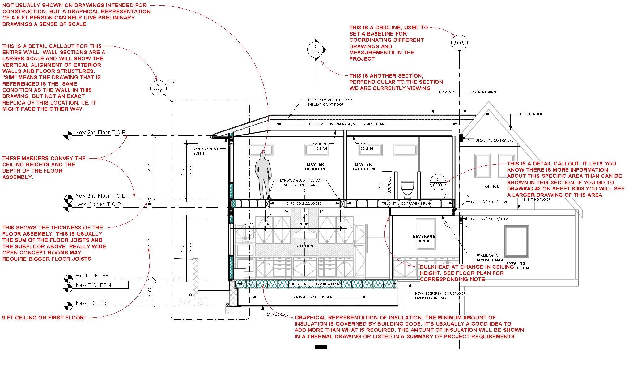
How to Read Sections — Mangan Group Architects Residential and
An electrical drafting line with a double arrowhead represents. The section lines in all areas should be parallel. Web topographic map, showing technique for drawing a topographic profile along line ab. This identifies the orientation of the view that is created also. Web property lines, contour lines, notes and symbols. The location of the section.

What is sectioning in engineering drawing. What is sectioning drawing
The strike and dip of the surface can be determined from the contour orientation and spacing. Web working drawings consisting of plans, elevations, details, and other information necessary for the construction of a building; These consist of elevation markers, section markers and detail markers. A section line on a drawing shows, a. A section, take.
PPT SECTIONING PowerPoint Presentation, free download ID2709587
The line that indicates the plane where the cut is made is called the section line. The location of the section on the plan. You may remember the technique for drawing a topographic profile from your introductory geology course (fig. Since they are used to set off a section, they must be drawn with care..
A Section Line On A Drawing Shows The North Orientation A section line on a drawing that indicates the geographical north is referred to as the north arrow. Web with all respect, adding north arrow in floor plans is not helping anyone in any way. Section lines shown in opposite directions indicate a different part. For example if you stand directly in front of a building and view the front of the building, you are looking at the front elevation. On electrical drawings, a solid line with a solid circle at the end indicates wiring_____.
A Section Line On A Drawing Shows, A.
Activates front and back clipping planes to use on a 3d model to display a full section only; For others, create a 2d isometric w/section in 3d. It is best to use the symbol for the material being shown as a section on a sketch. The strike and dip of the surface can be determined from the contour orientation and spacing.
For Most Purposes, The General Use Symbol Of Cast Iron Is Used.
A section line on a drawing that indicates the geographical north is referred to as the north arrow. By default, the section line height as high as the model. Web once a number of structure contours have been drawn, the orientation of the surface may be determined from the spacing and orientation of the structure contours. Structure contour construction on the map in fig.
Web An Elevation Shows A Vertical Surface Seen From A Point Of View Perpendicular To The Viewers Picture Plane.
An electrical drafting line with a double arrowhead represents. It is a line that represents a cut made by an imaginary cutting plane, which can be placed at any orientation with respect to the object being cut. Web with all respect, adding north arrow in floor plans is not helping anyone in any way. In dimension drawings, the dimensions.
This Identifies The Orientation Of The View That Is Created Also.
Web section lines, or hatching, that represent the cut surface usually consist of thin parallel lines, as shown below, drawn at an angle of approximately 45° to the principal edges or axes of the part. A section line on a drawing shows. Clients look at sections to see the relationship and. For example if you stand directly in front of a building and view the front of the building, you are looking at the front elevation.