
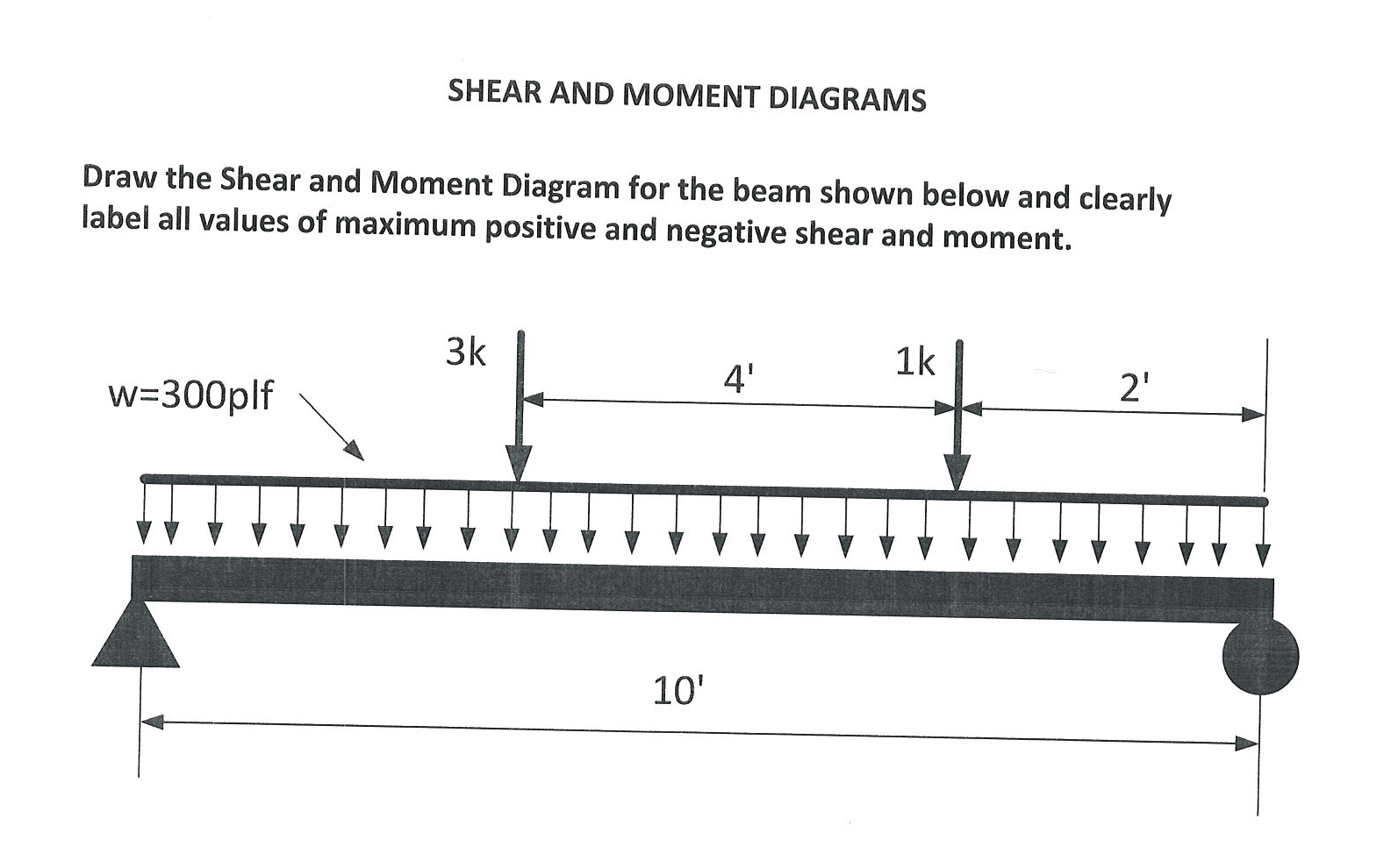
Draw Shear And Moment Diagrams For The Beam
Draw Shear And Moment Diagrams For The Beam - B will be to write the and mcnnent quations. Skyciv beam tool guides users along a professional beam calculation workflow, culminating in the ability to view and determine if they comply with your region's design codes. Also draw shear force diagram (sfd) and bending moment diagram (bmd). The internal forces give rise to two kinds of stresses on a transverse section of a beam: Draw the shear and moment diagrams for the beam.
Web you’ll understand how to model beam elements that resist axial force, shear forces and bending moments within the direct stiffness method. For the beam of figure 4: 200 lb ft b x 4 ft 4 ft 150 lb/ft 6 ft 200 lb ft a. Draw the shear and moment diagrams for the beam in (figure 1). 3 m 3 m x ab 200 n/m 400 n/m ans: Web this problem has been solved! Web steps to construct shear force and bending moment diagrams.

Learn How To Draw Shear Force And Bending Moment Diagrams Engineering
In each problem, let x be the distance measured from left end of the beam. Mechanical engineering questions and answers. Web this video explain how to draw shear force and bending moment diagram of a beam with a triangular distributed load acting on the beam. 3 m 3 m x ab 200 n/m 400 n/m.

Solved Draw the shear and moment diagrams for the beam.
3 m 3 m x ab 200 n/m 400 n/m ans: You'll get a detailed solution from a subject matter expert that helps you learn core concepts. Draw a free body diagram of the beam with global coordinates (x) calculate the reaction forces using equilibrium equations ( ∑ forces = 0 and ∑ moments =.
Solved Draw the Shear and Moment Diagram for the beam shown
∑ fy = 0 = − vr + p ⇒ vr = p. Web 100% (1 rating) step 1 reaction at support = ay ay = 8 × 1.5 + 6 = 18 view the full answer step 2 unlock answer unlock previous question next question transcribed image text: = deflection or deformation, in. Web.

Shear force and bending moment diagrams for a simply supported beam
If you’re not in the mood. Web r = span length of the bending member, in. Web 2) calculate the shear force and bending moment diagram of the beam as shown in the figure. Web this video explain how to draw shear force and bending moment diagram of a beam with a triangular distributed load.

Learn How To Draw Shear Force And Bending Moment Diagrams Engineering
V(x) = vr = p = constant. Web write shear and moment equations for the beams in the following problems. Web this video explain how to draw shear force and bending moment diagram of a beam with a triangular distributed load acting on the beam. Web write equations for the shear v and bending moment.

Solved Draw the shear and moment diagrams for the beam
Web this video explains how to draw shear force diagram and bending moment diagram with easy steps for a simply supported beam loaded with a concentrated load. The reactions shown on the diagram are determined from equilibrium equations as follows: Label all significant points on each diagram. Web this problem has been solved! R =.
Solved Draw the shear and moment diagrams for the beam.
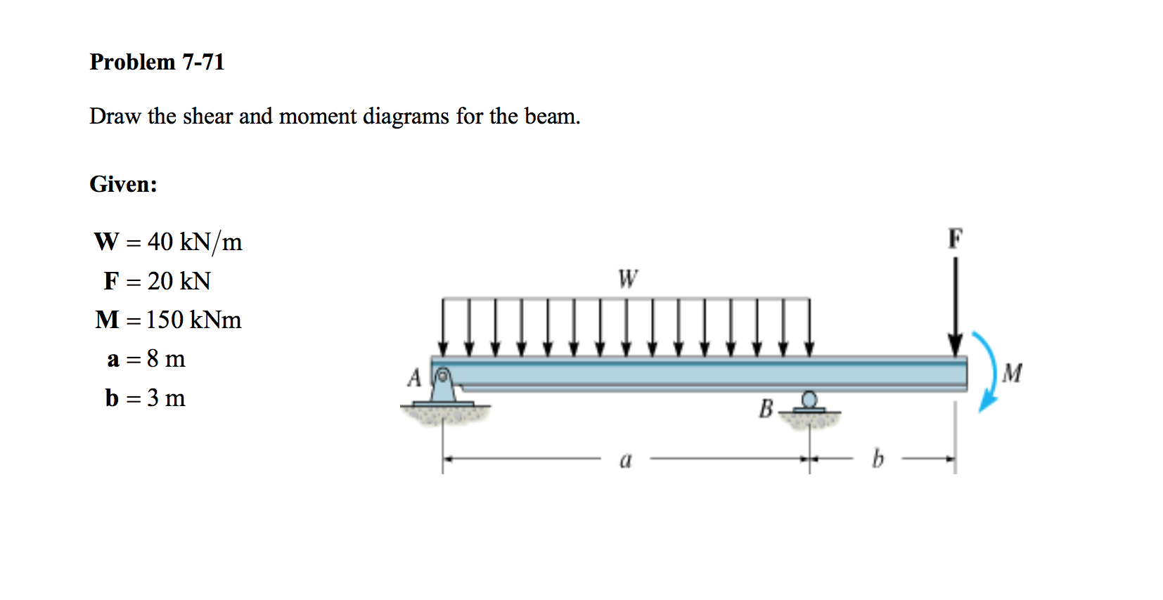
R − 6 × 9 1 (9) 9 × 0 2 3 ∴ r = 9 kn a 20 kn 40 kn/m cl 150 kn m 8 m 3 m prob. V(x) = vr = p = constant. The bending moment diagram of the. Mechanical engineering questions and answers. Internal forces 6.2 shear/moment diagrams 6.2.1.

Solved Draw the shear and moment diagrams for the beam, and
Web this video explains how to draw shear force diagram and bending moment diagram with easy steps for a simply supported beam loaded with a concentrated load. R − 6 × 9 1 (9) 9 × 0 2 3 ∴ r = 9 kn a Let a = 5.0 ft, b = 4.5 ft, p.

Solved Draw the shear and moment diagrams for the beam (a)
P = total concentrated load, lbs. Draw the shear and moment diagrams for the beam in (figure 1). V = shear force, lbs. Free body diagram of the given figure is given below; Web the shear force and the bending moment usually vary continuously along the length of the beam. In each problem, let x.

Drawing Shear and Moment Diagrams for Beam YouTube
B will be to write the and mcnnent quations. Web r = span length of the bending member, in. ∑ fy = 0 = − vr + p ⇒ vr = p. W = total uniform load, lbs. Label all significant points on each diagram. Web in solid mechanics, a bending moment is the reaction.
Draw Shear And Moment Diagrams For The Beam Web the shear force and the bending moment usually vary continuously along the length of the beam. 20 kn 40 kn/m cl 150 kn m 8 m 3 m prob. Example 1 draw the shear force and bending moment diagrams for the beam shown below a) determine the reactions at the supports. Web steps to construct shear force and bending moment diagrams. Let a = 5.0 ft, b = 4.5 ft, p = 21 kips, and w = 3.0 kips/ft.
This Page Will Walk You Through What Shear Forces And Bending Moments Are, Why They Are Useful, The Procedure For Drawing The Diagrams And Some Other Keys Aspects As Well.
Draw the shear and moment diagrams for the cantilevered beam. We go through breaking a beam into segments, and then we learn about the relationships between shear force. ∑ fy = 0 = − vr + p ⇒ vr = p. Web the shear force and the bending moment usually vary continuously along the length of the beam.
Web Steps To Construct Shear Force And Bending Moment Diagrams.
Internal forces 6.2 shear/moment diagrams 6.2.1 what are shear/moment diagrams? Also, draw shear and moment diagrams, specifying values at all change of loading positions and at. Free body diagram of the given figure is given below; (a) draw complete shear and moment diagrams (b) design the cross section of the beam, knowing that the grade of timber used has an allowable normal stress of 1,200psi and an allowable shear stress of 120psi.
Web This Video Explains How To Draw Shear Force Diagram And Bending Moment Diagram With Easy Steps For A Simply Supported Beam Loaded With A Concentrated Load.
[1] [2] the most common or simplest structural element subjected to bending moments is the beam. Web write equations for the shear v and bending moment m for any section of the beam in the interval ab. Shear force and bending moment diagrams are analytical tools used in conjunction with structural analysis to help perform structural design by determining the value of shear forces and bending moments at a given point of a structural element such. Web shear force and bending moment diagrams are powerful graphical methods that are used to analyze a beam under loading.
W = Load Per Unit Length, Lbs./In.
For the beam and loading shown: R − 6 × 9 1 (9) 9 × 0 2 3 ∴ r = 9 kn a Let a = 5.0 ft, b = 4.5 ft, p = 21 kips, and w = 3.0 kips/ft. Skyciv beam tool guides users along a professional beam calculation workflow, culminating in the ability to view and determine if they comply with your region's design codes.