Draw Single Line Diagram
Draw Single Line Diagram - Below is the csa z462 single line diagram definition: Three phases are denoted by a single conductor i.e., power system is assumed in a balanced steady state. You can bring your ideas to life with our most capable image model, dall·e 3. This is autocad tutorial for electrical engineers. Web wiring diagrams are used to show control and signalization principle of operation inside switchboard.
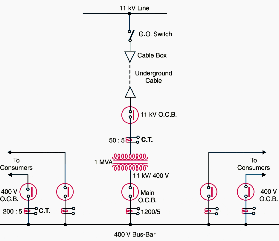
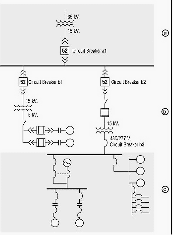
A single line can show all or part of a system. This diagram is used to visually represent the components of a power system, and is a valuable tool. You can use this autocad 2d electrical. Three phases are denoted by a single conductor i.e., power system is assumed in a balanced steady state. A diagram which shows, by means of single lines and graphic symbols, the course of an electric circuit or system of circuits and the component devices or parts used therein. This drawing shall show the overall power system from the utility to the distribution equipment.single line drawings include overall power single line(s), medium voltage switchgear single lines, unit substation single lines, mcc single lines and pdp single lines. Web this tutorial shows how to draw single line diagram in electrical using autocad step by step from scratch.
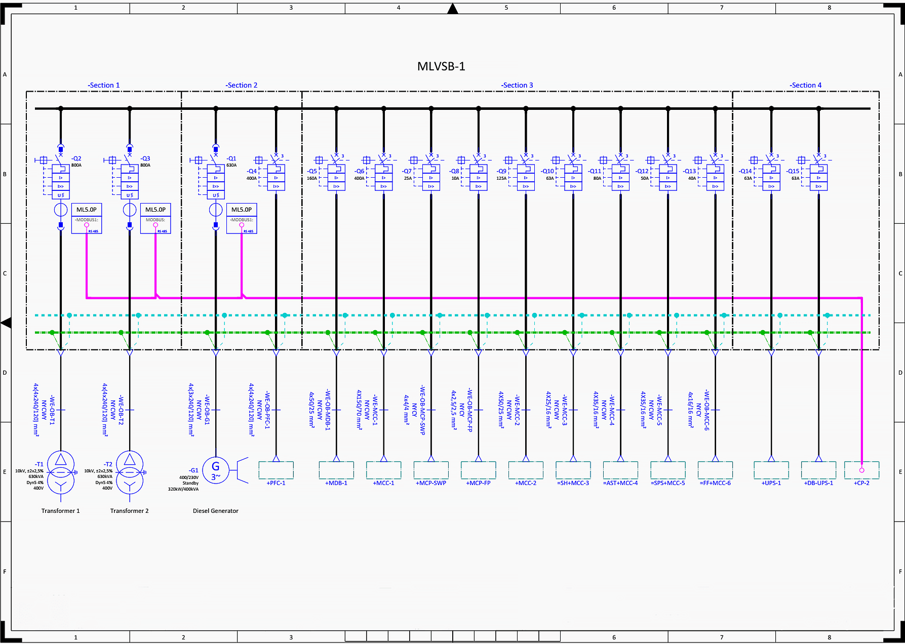
What Is A Single Line Diagram, And How Can You Read And Understand One
This drawing shall show the overall power system from the utility to the distribution equipment.single line drawings include overall power single line(s), medium voltage switchgear single lines, unit substation single lines, mcc single lines and pdp single lines. This diagram is used to visually represent the components of a power system, and is a valuable.
How To Calculate and Draw a Single Line Diagram For The Power System EEP
It is the first step in making a critical response plan and lets you get to know the layout and design of your facility’s electrical distribution system. Web a single line diagram is method of simplified representation of a three phase power system. Every component included in the sld will be explained, and clarify why.
AutoCAD Single Line Diagram Drawing Tutorial for Electrical Engineers
Web in this video we learn how to draw the single line/schematic diagram/one line diagrams with calculations also we can learn basic symbols used in single line. Web in the single line diagram, the system component is usually drawn in the form of their symbols. This diagram is used to visually represent the components of.
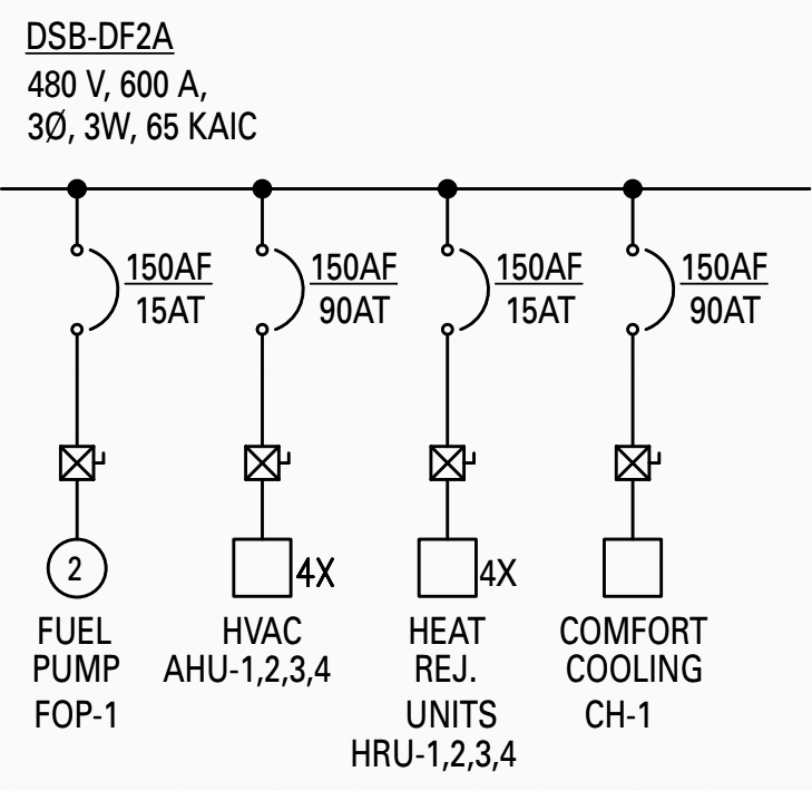
The essentials of designing MV/LV single line diagrams (symbols
You can use this autocad 2d electrical. Below is the csa z462 single line diagram definition: It is the first step in preparing a critical response plan, allowing you to become thoroughly familiar with the electrical distribution system layout and design in your facility. A diagram which shows, by means of single lines and graphic.
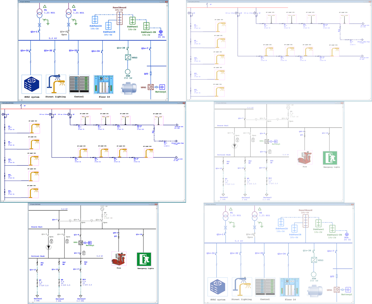
Intelligent One Line Diagram Electrical SingleLine Diagram ETAP
A diagram which shows, by means of single lines and graphic symbols, the course of an electric circuit or system of circuits and the component devices or parts used therein. You can use this autocad 2d electrical. Below is the csa z462 single line diagram definition: We then need to follow the line from msb.
How To Calculate and Draw a Single Line Diagram For The Power System EEP
Web in this video, theelectricalguy explains the electrical single line diagram of a power system. Below is the csa z462 single line diagram definition: It is the first step in preparing a critical response plan, allowing you to become thoroughly familiar with the electrical distribution system layout and design in your facility. Web we usually.
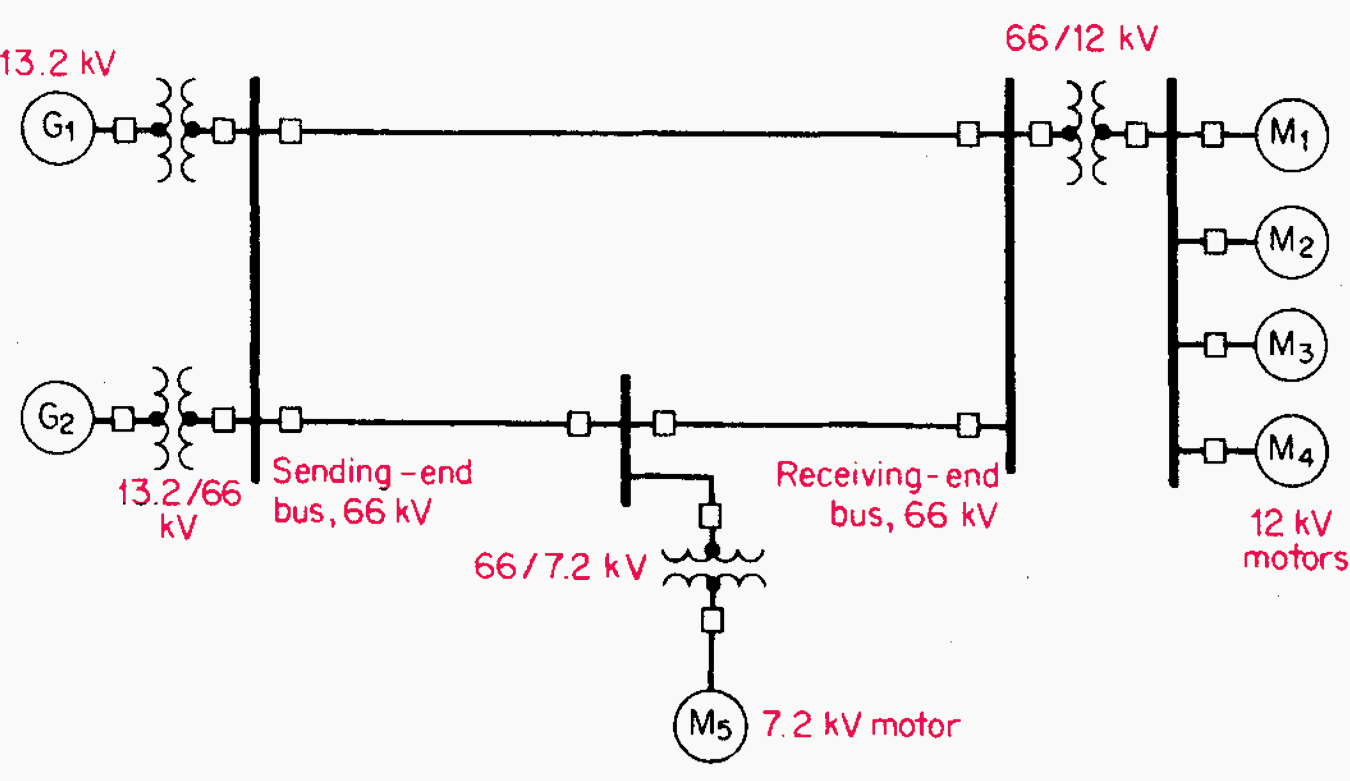
Single line diagrams of substations 66/11 kV and 11/0.4 kV EEP
It shows the power distribution path from the incoming power source to each load, the arrangement of the major electrical system components and their connections in a simple view. Web plant single line diagram. Web we usually depict the electrical distribution system by a graphic representation called a single line diagram (sld). Remember the lines.
Learn To Interpret Single Line Diagram (SLD) EEP
Web this final set of approved design development drawings, which include the single line diagram, are used as the basis for the development of the construction drawings. It is the first step in preparing a critical response plan, allowing you to become thoroughly familiar with the electrical distribution system layout and design in your facility..
Electrical Single Line Diagram StanleyknoeColeman
Every component included in the sld will be explained, and clarify why it is mentioned in the diagram and why it is functional. Use the electrical engineering drawing type in visio professional or visio plan 2 go create electrical and electronic schematic diagrams. Web wiring diagrams are used to show control and signalization principle of.
how to draw single line diagram electrical Wiring Work
Usually they are given in form of electrical circuits between two lines which are representing control voltage potentials. Web wiring diagrams are used to show control and signalization principle of operation inside switchboard. A single line can show all or part of a system. It shows the power distribution path from the incoming power source.
Draw Single Line Diagram Web this tutorial shows how to draw single line diagram in electrical using autocad step by step from scratch. Usually they are given in form of electrical circuits between two lines which are representing control voltage potentials. Web we usually depict the electrical distribution system by a graphic representation called a single line diagram (sld). Every component included in the sld will be explained, and clarify why it is mentioned in the diagram and why it is functional. Moving into the construction document phase of a project, alterations are made to the design development electrical drawing set.
Web This Tutorial Shows How To Draw Single Line Diagram In Electrical Using Autocad Step By Step From Scratch.
A diagram which shows, by means of single lines and graphic symbols, the course of an electric circuit or system of circuits and the component devices or parts used therein. Every component included in the sld will be explained, and clarify why it is mentioned in the diagram and why it is functional. It shows the power distribution path from the incoming power source to each load, the arrangement of the major electrical system components and their connections in a simple view. Web this final set of approved design development drawings, which include the single line diagram, are used as the basis for the development of the construction drawings.
This Is Autocad Tutorial For Electrical Engineers.
Web wiring diagrams are used to show control and signalization principle of operation inside switchboard. You can bring your ideas to life with our most capable image model, dall·e 3. Web in this video, theelectricalguy explains the electrical single line diagram of a power system. Moving into the construction document phase of a project, alterations are made to the design development electrical drawing set.
Create Images Simply By Describing Them In Chatgpt.
We then need to follow the line from msb 2 upstream to see what is feeding msb 2. Web the recently added movie on the cadline community entitled “producing single line diagrams” shows you how to create a single line diagram alternatively known as topology, cable block or field. Usually they are given in form of electrical circuits between two lines which are representing control voltage potentials. It is the first step in making a critical response plan and lets you get to know the layout and design of your facility’s electrical distribution system.
Generator And Transformer Connections, Star, Delta And Neutral Earthing Are Indicated By Symbols Drawn By The Side Of The Representation Of These Elements.
We start at the top of the diagram and follow the equipment down. This condenses the space and complexity of the diagram for simpler troubleshooting. Circuit breakers are represented by rectangular blocks. Three phases are denoted by a single conductor i.e., power system is assumed in a balanced steady state.

