
Draw The Shear And Moment Diagram For The Beam
Draw The Shear And Moment Diagram For The Beam - The diagram which represents the different effective force on the beam is known as shear and moment diagrams. Web draw the shear and moment diagrams for the beam. Web write equations for the shear v and bending moment m for any section of the beam in the interval ab. We go through breaking a beam into segments, and then we learn about the relationships between shear force. Web shear force and bending moment diagrams are analytical tools used in conjunction with structural analysis to help perform structural design by determining the value of shear forces and bending moments at a given point of a structural element such as a beam.
∑ m = 0 ; The diagram shows a beam which is simply supported (free to rotate and. R − 6 × 9 1 (9) 9 × 0 2 3 ∴ r = 9 kn a Web shear force and bending moment diagrams are analytical tools used in conjunction with structural analysis to help perform structural design by determining the value of shear forces and bending moments at a given point of a structural element such as a beam. V(x) = vr = p = constant. This page will walk you through what shear forces and bending moments are, why they are useful, the procedure for drawing the diagrams and some other keys aspects as well. ∑ fy = 0 = − vr + p ⇒ vr = p.
Solved Draw the shear and moment diagrams for the beam.
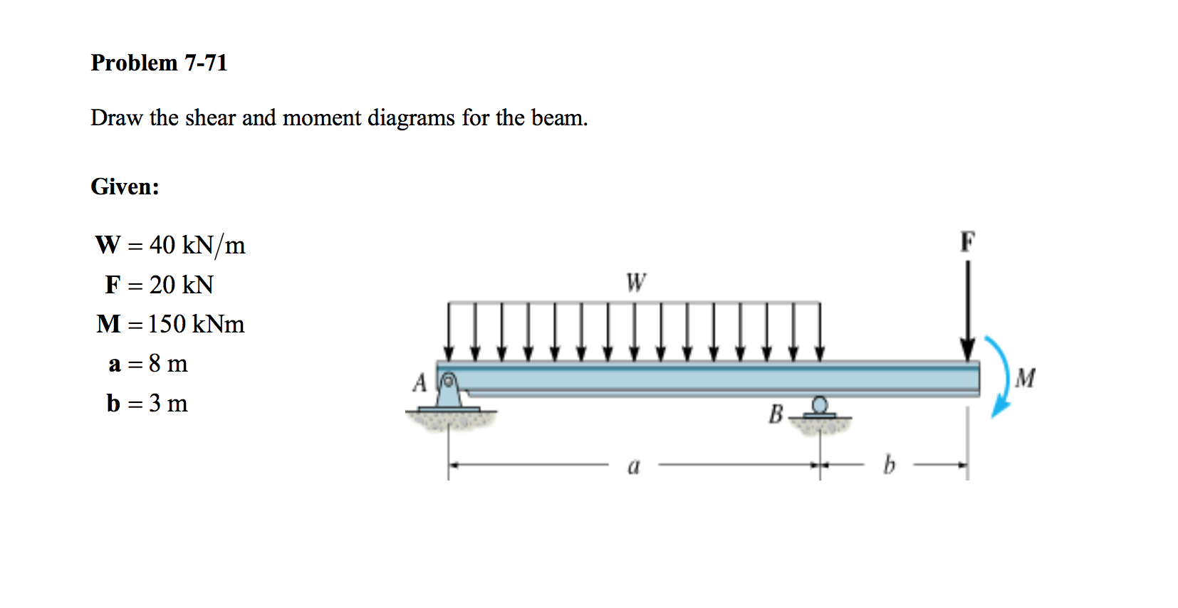
[1] [2] the most common or simplest structural element subjected to bending moments is the beam. The bending moment diagram of the. The reactions shown on the diagram are determined from equilibrium equations as follows: 20 kn 40 kn/m cl 150 kn m 8 m 3 m prob. Web you will be fully competent in.

Solved Draw the shear and moment diagrams for the beam (a)
(1) normal stress that is caused by bending moment and. Web you will be fully competent in drawing shear force and bending moment diagrams for statically determinate beams and frames. In general the process goes like this:1) calcul. The shear and bending moment at x are then. Web this video explains how to draw shear.

Learn How To Draw Shear Force And Bending Moment Diagrams Engineering
Web learn to draw shear force and moment diagrams using 2 methods, step by step. In each problem, let x be the distance measured from left end of the beam. I have given in the example below. Bending moment diagram this is a graphical representation of the variation of the bending moment on a segment.

Solved Draw the shear and moment diagrams for the beam, and
Web learn to draw shear force and moment diagrams using 2 methods, step by step. In a simply supported beam, the only vertical force is the 5kn/m force, which when multiplied by the length of the member (l = 10) we get 5*10 = 50 kn. 20 kn 40 kn/m cl 150 kn m 8.

Drawing Shear and Moment Diagrams for Beam YouTube
Web the vertical force acting o the beam or any structure is known as shear force and the turning effect on the structure is known as the bending moment. Bending moment diagram this is a graphical representation of the variation of the bending moment on a segment or the entire length of a beam or.

Solved Draw the shear and moment diagrams for the beam.
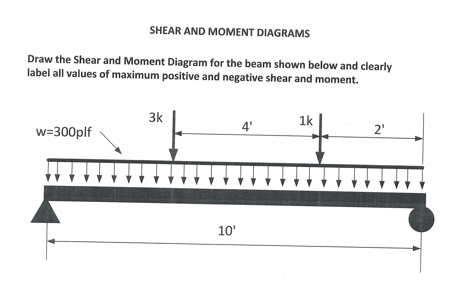
Draw the shear and moment diagrams for the beam, and determine the shear and moment throughout the beam as functions of x for 0 ≤ x ≤ 6ft and 6ft ≤ x ≤ 10ft. If the cross section of the beam is rectangular with height of 0.2ft and width of 0.1ft, and the beam has.
Solved Draw the Shear and Moment Diagram for the beam shown
Web figures 1 through 32 provide a series of shear and moment diagrams with accompanying formulas for design of beams under various static loading conditions. The bending moment diagram of the. Web you will be fully competent in drawing shear force and bending moment diagrams for statically determinate beams and frames. Example 1 draw the.

Shear force and bending moment diagrams for beams pdf
Web shear force and bending moment diagrams are analytical tools used in conjunction with structural analysis to help perform structural design by determining the value of shear forces and bending moments at a given point of a structural element such as a beam. 20 kn 40 kn/m cl 150 kn m 8 m 3 m.

Learn How To Draw Shear Force And Bending Moment Diagrams Engineering
Web you will be fully competent in drawing shear force and bending moment diagrams for statically determinate beams and frames. Web draw the shear and moment diagrams for the beam. You will understand the relationship between external loading and the shear forces and bending moments they induce. Web this is an example problem that will.

Solved Draw the shear and moment diagrams for the beam
∑ m = 0 ; ∑ fy = 0 = − vr + p ⇒ vr = p. Example 1 draw the shear force and bending moment diagrams for the beam shown below a) determine the reactions at the supports. If you’re not in the mood. You'll get a detailed solution from a subject matter.
Draw The Shear And Moment Diagram For The Beam You'll get a detailed solution from a subject matter expert that helps you learn core concepts. (see above) sum up the forces in the vertical direction. Bending moment diagram this is a graphical representation of the variation of the bending moment on a segment or the entire length of a beam or frame. The internal forces give rise to two kinds of stresses on a transverse section of a beam: Web since the function for the bending moment is parabolic, the bending moment diagram is a curve.
Web The Vertical Force Acting O The Beam Or Any Structure Is Known As Shear Force And The Turning Effect On The Structure Is Known As The Bending Moment.
In a simply supported beam, the only vertical force is the 5kn/m force, which when multiplied by the length of the member (l = 10) we get 5*10 = 50 kn. Web write equations for the shear v and bending moment m for any section of the beam in the interval ab. (see above) sum up the forces in the vertical direction. Web since the function for the bending moment is parabolic, the bending moment diagram is a curve.
R − 6 × 9 1 (9) 9 × 0 2 3 ∴ R = 9 Kn A
In general the process goes like this:1) calcul. You'll get a detailed solution from a subject matter expert that helps you learn core concepts. ∑ m = 0 ; Web this is an example problem that will show you how to graphically draw a shear and moment diagram for a beam.
Web Draw The Shear And Moment Diagrams For The Beam, And Determine The Shear And Moment In The Beam As Functions Of X For 0 X 4 Ft, 4 Ft X 10 Ft, And 10 Ft X 14 Ft 250 Lb 250 Lb 150 Lb/Ft 6 Ft 4 Ft 4 Ft Prob.
Web write shear and moment equations for the beams in the following problems. The internal forces give rise to two kinds of stresses on a transverse section of a beam: Web in solid mechanics, a bending moment is the reaction induced in a structural element when an external force or moment is applied to the element, causing the element to bend. I have given in the example below.
Draw A Free Body Diagram Of The Beam With Global Coordinates (X) Calculate The Reaction Forces Using Equilibrium Equations ( ∑ Forces = 0 And ∑ Moments = 0 ).
∑ fy = 0 = − vr + p ⇒ vr = p. [1] [2] the most common or simplest structural element subjected to bending moments is the beam. In each problem, let x be the distance measured from left end of the beam. The diagram which represents the different effective force on the beam is known as shear and moment diagrams.