
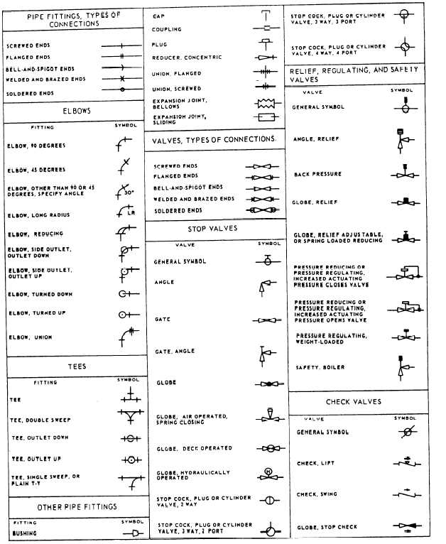
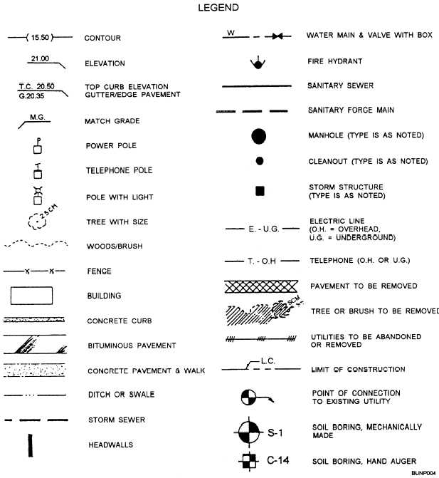
Drawing Symbols Meaning
Drawing Symbols Meaning - The symbols and abbreviations represent various components, processes, and measurements used in engineering design. Web this chapter covers all of the major gd&t tools for engineering drawings including dimensions, tolerances, gd&t symbols, datums, feature control frames and more May be added to a drawing in a note form or inserted into the title block. Web mechanical engineering solution — 8 libraries are available with 602 commonly used mechanical drawing symbols in mechanical engineering solution, including libraries called bearings with 59 elements of roller and ball bearings, shafts, gears, hooks, springs, spindles and keys; These symbols often depict standard shapes such as circles, squares, triangles, and rectangles, which can represent anything from simple geometric features to complex mechanical parts.
Web filled or unfilled datum feature symbol target area size (when used) 2 h datum target straightness flatness form circularity cylindricity 60 ° profile profile of a line profile of a surface number datum target symbol without area size datum target symbol with area size datum target symbol 90 ° 2 h target point target line position You can find the list of common engineering drawing abbreviations. There are many variations of the surface texture symbol but most often it is used with a microinch or micrometer value callout that specifies the roughness of a surface. Unlike a model, engineering drawings offer more specific detail and requirements, such as: Web location of symbols on a drawing these symbols show maximum and minimum roughness values. Click on the links below to learn more about each gd&t symbol or concept, and be sure to download the free wall chart for a quick reference when at your desk or. A weld symbol defines the type of geometry for the welding joint.

Engineering Drawing Symbols And Their Meanings Pdf at PaintingValley
Web the technical engineering drawing abbreviations we outline here are the terms used in the manufacturing and inspection of parts and assemblies. Web this page explains the 16 symbols used in gd&t, and the classification thereof. Web filled or unfilled datum feature symbol target area size (when used) 2 h datum target straightness flatness form.

Engineering Drawing Symbols And Their Meanings Pdf at GetDrawings
Web mechanical engineering solution — 8 libraries are available with 602 commonly used mechanical drawing symbols in mechanical engineering solution, including libraries called bearings with 59 elements of roller and ball bearings, shafts, gears, hooks, springs, spindles and keys; Web diameter symbol — a symbol indicating that the dimension shows the diameter of a circle..

ANSI Standard JSTD710 Architectural Drawing Symbols Bedrock Learning
Gd&t is used to define the nominal (theoretically. The following is a short list of symbols that normally appear on a technical drawing and need understanding. Web start with our guide to blueprints and learn all the basic elements of engineering drawings including symbols, terminology and lots of examples. To specify a spherical zone, the.

Engineering Drawing Symbols And Their Meanings Pdf at PaintingValley
The symbols and abbreviations represent various components, processes, and measurements used in engineering design. Web start with our guide to blueprints and learn all the basic elements of engineering drawings including symbols, terminology and lots of examples. Web the letter ‘ h’ represents the predominant character height on a drawing. The true position theory and.

Engineering Drawing Symbols And Their Meanings Pdf at PaintingValley
The symbol used is the greek letter phi ø. If a symbol dimension is shown as 1.5h, and the predominant character height on the drawing is to be 3mm, then the symbol dimension is 4.5mm (1.5 x 3mm). Web filled or unfilled datum feature symbol target area size (when used) 2 h datum target straightness.

How To Read Architectural Drawings Symbols The Architect
May be added to a drawing in a note. These symbols often depict standard shapes such as circles, squares, triangles, and rectangles, which can represent anything from simple geometric features to complex mechanical parts. Web one of the primary purposes of engineering drawing symbols is to represent various objects and components within a design. To.

Engineering Drawing Symbols And Their Meanings Pdf at PaintingValley
The symbol used is the greek letter phi ø. Web a symbol for defining the surface finish of a part. Web a convenient guide for geometric dimensioning and tolerancing (gd&t) symbols at your fingertips. Need to know for dispelling uncertainty in drawings. Web engineering drawing abbreviations are a set of standardized symbols and abbreviations used.

ANSI Standard JSTD710 Architectural Drawing Symbols Bedrock Learning
A weld symbol defines the type of geometry for the welding joint. A common use is to specify the geometry necessary for the construction of a component and is called a detail drawing. To specify a spherical zone, the symbol is the letter ‘s’ followed by the diameter symbol (⌀). An engineering drawing is a.
Engineering Drawing Symbols And Their Meanings Pdf at PaintingValley
Web the letter ‘ h’ represents the predominant character height on a drawing. If a symbol dimension is shown as 1.5h, and the predominant character height on the drawing is to be 3mm, then the symbol dimension is 4.5mm (1.5 x 3mm). Web the first symbol shows the type of tolerance zone. The following is.
Civil Engineering Drawing Symbols And Their Meanings at PaintingValley
This list includes abbreviations common to the vocabulary of people who work with engineering drawings in the manufacture and inspection of parts and assemblies. Web filled or unfilled datum feature symbol target area size (when used) 2 h datum target straightness flatness form circularity cylindricity 60 ° profile profile of a line profile of a.
Drawing Symbols Meaning You can find the list of common engineering drawing abbreviations. A common use is to specify the geometry necessary for the construction of a component and is called a detail drawing. Web diameter symbol — a symbol indicating that the dimension shows the diameter of a circle. This one is used when all the surfaces are to be machined to the same surface texture. Web a weld symbol is a pictorial profile that is attached to the reference line part of the welding symbol.
This One Is Used When All The Surfaces Are To Be Machined To The Same Surface Texture.
Web this chapter covers all of the major gd&t tools for engineering drawings including dimensions, tolerances, gd&t symbols, datums, feature control frames and more A diameter symbol (⌀) signifies a diametric zone (cylindrical tolerance zone). The true position theory and the specification of tolerance zones are also explained. Web a weld symbol is a pictorial profile that is attached to the reference line part of the welding symbol.
Web Engineering Working Drawing Basics Is A Pdf Document That Introduces The Fundamental Principles And Practices Of Engineering Drawing.
Web engineering drawing abbreviations and symbols are used to communicate and detail the characteristics of an engineering drawing. Usually, a number of drawings are necessary to completely specify even a simple component. May be added to a drawing in a note form or inserted into the title block. Web start with our guide to blueprints and learn all the basic elements of engineering drawings including symbols, terminology and lots of examples.
Web The Technical Engineering Drawing Abbreviations We Outline Here Are The Terms Used In The Manufacturing And Inspection Of Parts And Assemblies.
To specify a spherical zone, the symbol is the letter ‘s’ followed by the diameter symbol (⌀). An engineering drawing is a type of technical drawing that is used to convey information about an object. Web engineering drawing abbreviations and symbols are used to communicate and detail the characteristics of an engineering drawing. In the absence of a symbol, we assume a total wide zone.
Gd&T Is Used To Define The Nominal (Theoretically.
Web this page explains the 16 symbols used in gd&t, and the classification thereof. Web the letter ‘ h’ represents the predominant character height on a drawing. Web filled or unfilled datum feature symbol target area size (when used) 2 h datum target straightness flatness form circularity cylindricity 60 ° profile profile of a line profile of a surface number datum target symbol without area size datum target symbol with area size datum target symbol 90 ° 2 h target point target line position The symbol used is the greek letter phi ø.