
Drawing Views Standard
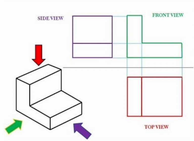
Drawing Views Standard - The width dimension is common to the front and top views. Web exploded views in drawings. Graphics is a visual communications language that include images, text, and numeric information. Web engineering graphics is used in the design process for visualization, communication, and documentation. Web the three standard views are the top, front, and right side.
They must be drawn in the positions shown below and they must be aligned. Standard drawing views' in the solidworks knowledge base. Web a drawing view represents the shape of the object when viewed from various standard directions, such as front, top, side, and so on. Web approach to modeling user interface sketching concepts drawings and detailing drawings drawings overview creating drawings drafting multiple drawings detailing and drawings solidworks file utilities driveworksxpress floxpress import and export using 3dexperience marketplace | make from solidworks Engineering drawings use standardised language and symbols. How drawing projecton system works. Web when you create a drawing from a part, curve, surface, or subassembly, you have the ability to create it without any views, by default, or with 4 standard views:
CME 475 Drawing Standards and Conventions
Standard drawing views' in the solidworks knowledge base. For simple parts one or two view drawings will. The convention for drawing views used in north america. Web engineering graphics is used in the design process for visualization, communication, and documentation. The two main types of views (or “projections”) used in drawings are: Usually, a number.
Engineering Drawing Views & Basics Explained Fractory
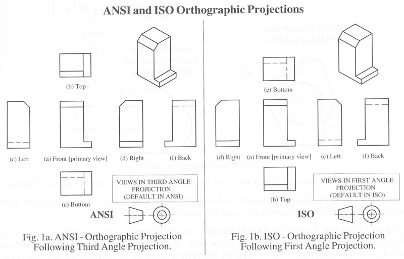
Engineering drawings use standardised language and symbols. Standard views, such as standard 3 views, various named model views (such as isometric), and relative views created automatically from the model. We will implement this rule to draw engineering drawings in 1st angle and 3rd angle projection systems. Web standards see also v t e an engineering.

types of section views in engineering drawing howisphotographyartistic
The two main types of views (or “projections”) used in drawings are: Web the standard views that generally begin a drawing are: Standard drawing views' in the solidworks knowledge base. 3.2 all drawings should be drafted using third angle projection on orthographic views. Web when you create a drawing from a part, curve, surface, or.

Basic Engineering Drawing Projection Knowledge Zone, The Online Support
A drawing file contains one or more drawing sheets on which 2 dimensional and/or 3 dimensional scaled views of the solid models contained in part, assembly, or presentation files. The convention for drawing views used in north america. Web engineering drawing standards manual. You can create an exploded drawing view from an existing exploded assembly.
A Definitive Guide to Drawing Views
This makes understanding the drawings simple with little to no personal interpretation possibilities. Web an engineering drawing is a subcategory of technical drawings. Model break views within drawings. Web according to the rule of orthographic projection: The height dimension is common to the front and side views. The scale of a drawing is defined as.
ENGRSEG4. Students will draw isometric and oblique drawings. Jake
The depth dimension is common to the top and side views. 3.2 all drawings should be drafted using third angle projection on orthographic views. Web an engineering drawing is a subcategory of technical drawings. The convention for drawing views used in north america. Web approach to modeling user interface sketching concepts drawings and detailing drawings.
Engineering Drawing Tutorials/Orthographic and sectional views ( T 11.3
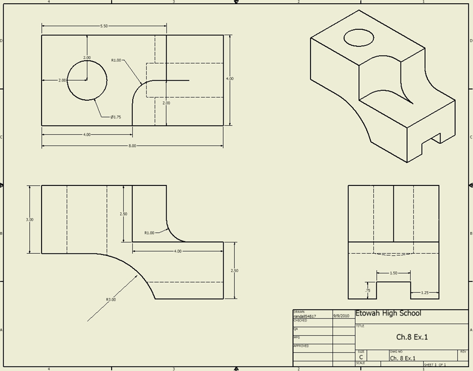
Usually, a number of drawings are necessary to completely specify even a simple component. Web standard drawing views d c b a a b c d 8 7 6 5 4 3 2 1 8 7 6 5 4 3 2 1 dimensions are in inches tolerances: Standard drawing views' in the solidworks knowledge base..
Engineering Drawing Views & Basics Explained Fractory
Web n0031q $72 select important information regarding asme pdfs description this standard establishes the requirements for creating orthographic, and pictorial views on engineering drawing graphic sheets and in models. The actual view is a model view, usually in the isometric orientation. Web the iasb is supported by technical staff and a range of advisory bodies..
How To Prepare A Perfect Technical Drawing Xometry Europe
The convention for drawing views used in north america. Web standard drawing views d c b a a b c d 8 7 6 5 4 3 2 1 8 7 6 5 4 3 2 1 dimensions are in inches tolerances: Usually, a number of drawings are necessary to completely specify even a simple.

Isometric Drawing Views
Most designers and engineers already know that. The actual view is a model view, usually in the isometric orientation. Web standards see also v t e an engineering drawing is a type of technical drawing that is used to convey information about an object. Web the iasb is supported by technical staff and a range.
Drawing Views Standard Web engineering graphics is used in the design process for visualization, communication, and documentation. Web approach to modeling user interface sketching concepts drawings and detailing drawings drawings overview creating drawings drafting multiple drawings detailing and drawings solidworks file utilities driveworksxpress floxpress import and export using 3dexperience marketplace | make from solidworks The width dimension is common to the front and top views. The horizontal plane is rotated in the clockwise direction to draw the projection view of a 3d object on a 2d plane. This makes understanding the drawings simple with little to no personal interpretation possibilities.
Web Standards See Also V T E An Engineering Drawing Is A Type Of Technical Drawing That Is Used To Convey Information About An Object.
Model break views within drawings. What you may not know is how much more you can do with your drawings, with just a little bit of guidance. This method can be used with both simple and complex objects and involves the use of a cutting plane that dictates what portion of the object you want to remove to reveal a more complex interior. Ahead of the issb standards—ifrs s1 and ifrs s2—coming into effect in january 2024, the international sustainability standards board (issb) is providing new and updated resources to help companies apply the standards.
A Common Use Is To Specify The Geometry Necessary For The Construction Of A Component And Is Called A Detail Drawing.
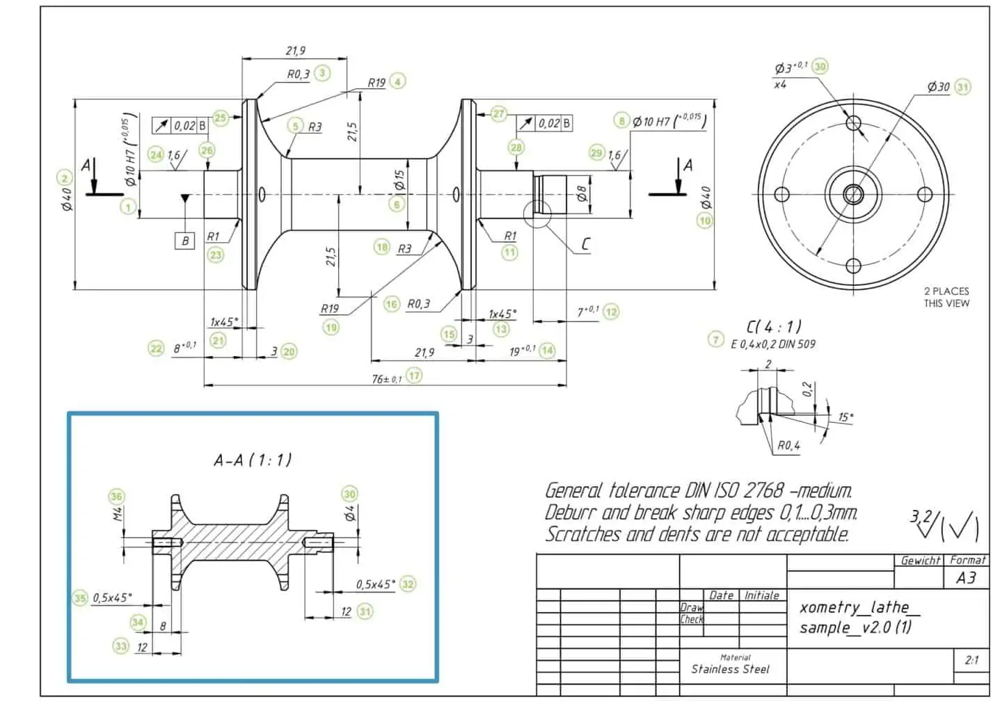
All engineering directorate design organizations and their contractors shall adhere to the requirements of this manual when preparing gsfc engineering documentation for flight hardware and ground support systems. Web engineering drawing standards manual. The scale of a drawing is defined as the ratio of a distance on the drawing to the corresponding distance on the actual object. Web according to the rule of orthographic projection:
Web Standard Drawing Views D C B A A B C D 8 7 6 5 4 3 2 1 8 7 6 5 4 3 2 1 Dimensions Are In Inches Tolerances:
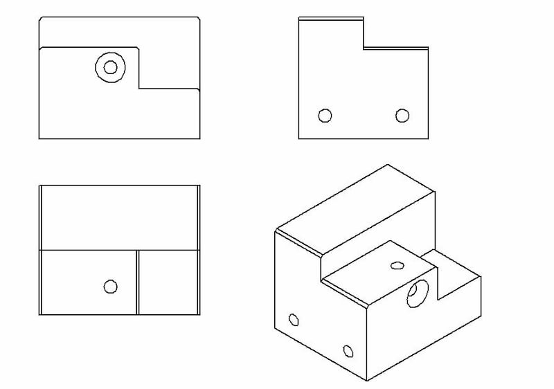
The purpose is to convey all the information necessary for manufacturing a product or a part. Graphics is a visual communications language that include images, text, and numeric information. Web a drawing view represents the shape of the object when viewed from various standard directions, such as front, top, side, and so on. How the views are laid out on a drawing depends on whether 3 rd angle or 1 st angle projection is being used.
Web The Iasb Is Supported By Technical Staff And A Range Of Advisory Bodies.
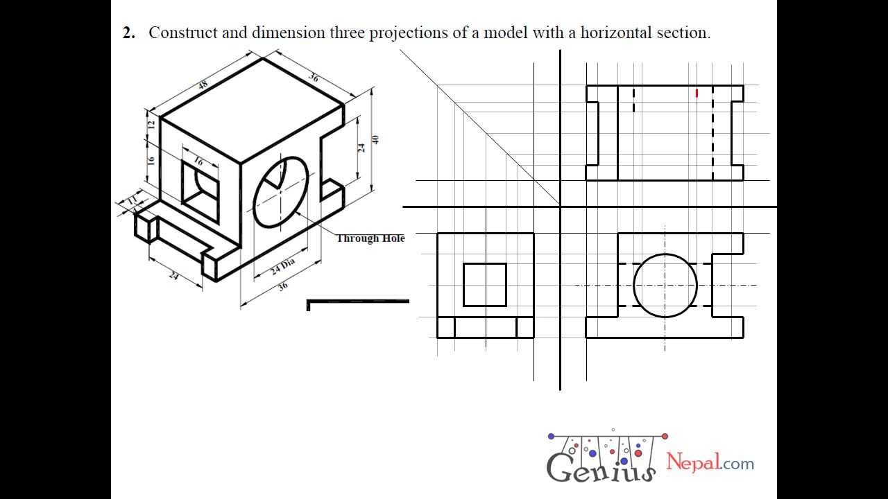
We will implement this rule to draw engineering drawings in 1st angle and 3rd angle projection systems. Section views are used extensively to show features of an object or an assembly that are not easily visible from the exterior. Orthographic views can show us an object viewed from each direction. The two main types of views (or “projections”) used in drawings are: