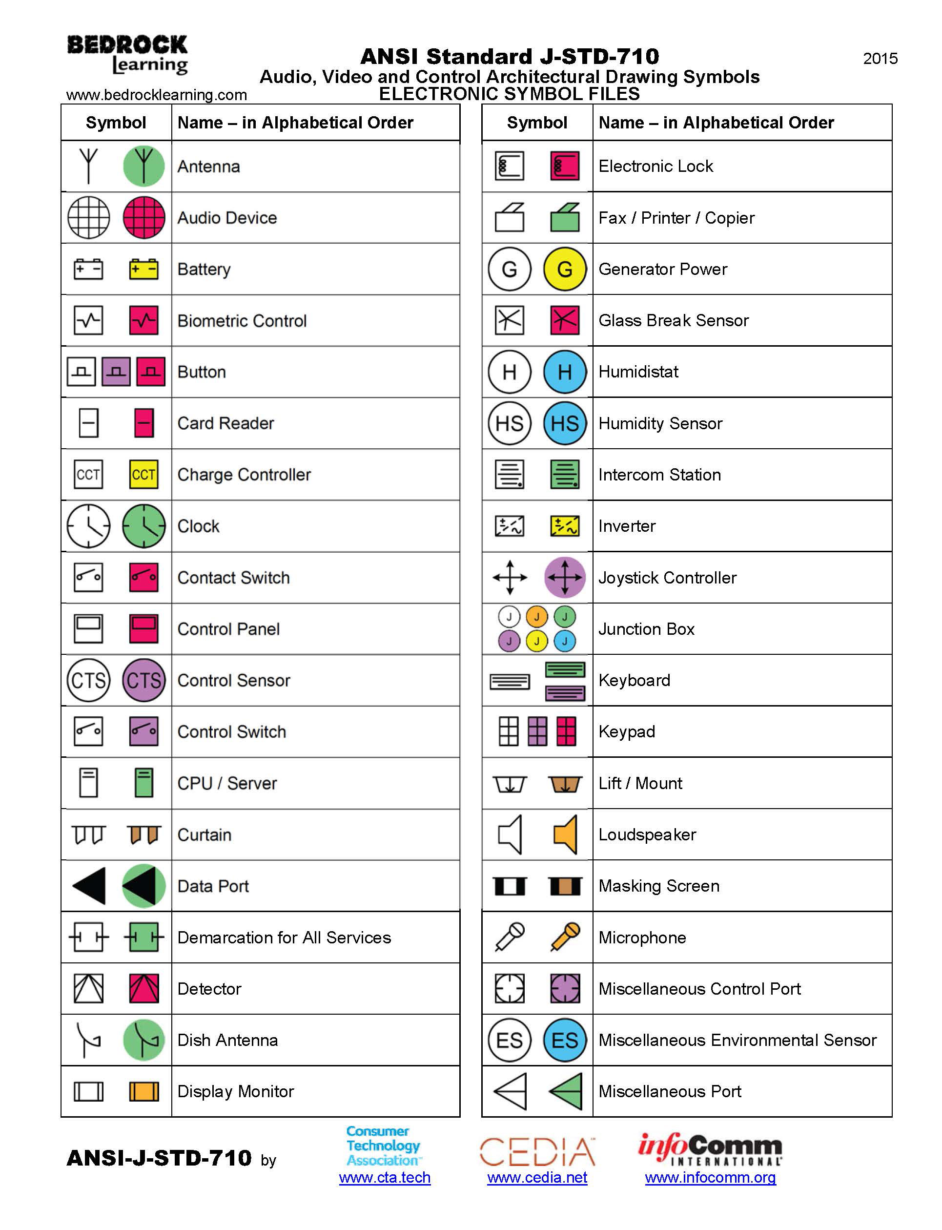
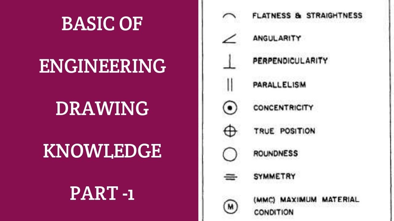
Engineering Symbols For Drawings
Engineering Symbols For Drawings - Web engineering drawing symbols are simple to pick up and use once you understand how to read them. Web engineering drawing symbols are graphical representations used to communicate information about the design and construction of engineering components and systems. The flatness tolerance references two parallel planes (parallel to the surface. Web in this post, we’ll go over the basics of how to read engineering drawing symbols. Web basic symbols used in engineering drawings by kelly curran glenn sokolowski.
They are used to convey important information such as dimensions, materials, and tolerances in a standardized and universally understood manner. Web engineering drawing symbols represent views of several geometry types such as surfaces (flat, cylindrical, spherical & toroidal), lines (linear, reference & centerlines), points (center & intersection), and also some standard views for orthographic projections, section view, and auxiliary views. Most symbols have been in y14.5 since at least 1994. The engineering drawings prepared by. Here are more commonly used engineering drawing symbols and design elements as below. Using abbreviations and symbols allows for concise representation, making the drawings easier to read and understand. An engineering (or technical) drawingis a graphical representation of a part, assembly, system, or structure and it can be produced using freehand, mechanical tools, or computer methods.
Engineering Drawing Symbols And Their Meanings Pdf at PaintingValley
Web the following is a list of symbols that are commonly found in engineering drawings: In the quiz that completes the activity, they associate these symbols with machining applications. Web geometric tolerances are specified using symbols on a drawing. How to read symbols in an engineering drawing? Web engineering drawings use standardized language and symbols.
Architectural Drawing Symbols Free Download at GetDrawings Free download
An engineering drawing completely defines every detail of the part, including its: Web 目录 why abbreviations and symbols are needed for engineering drawing? Web gd&t flatness is a common symbol that references how flat a surface is regardless of any other datum’s or features. The flatness tolerance references two parallel planes (parallel to the surface..
Engineering Drawing Symbols And Their Meanings Pdf at PaintingValley
Web 目录 why abbreviations and symbols are needed for engineering drawing? Web engineering drawing symbols represent views of several geometry types such as surfaces (flat, cylindrical, spherical & toroidal), lines (linear, reference & centerlines), points (center & intersection), and also some standard views for orthographic projections, section view, and auxiliary views. How to read symbols.
Types of Engineering Drawing Symbols and Uses इंजीनियरिंग ड्राइंग के
Web in this post, we’ll go over the basics of how to read engineering drawing symbols. Unlike a model, engineering drawings note much more specific information and requirements, such as: Web 目录 why abbreviations and symbols are needed for engineering drawing? This guide is designed to help you create a clear engineering drawing understanding that.
How To Read Architectural Drawings Symbols The Architect
Web engineering drawings (aka blueprints, prints, drawings, mechanical drawings) are a rich and specific outline that shows all the information and requirements needed to manufacture an item or product. Web are quite common on engineering drawings. Web geometric tolerances are specified using symbols on a drawing. Web engineering drawings use standardized language and symbols to.
Engineering Drawing Symbols And Their Meanings Pdf at PaintingValley
Basic types of symbols used in engineering drawings are countersink, counterbore, spotface, depth, radius, and diameter. These are only a few of the total number of symbol and abbreviations available in each area, and are produced here to make you aware of what area of engineering the symbols and Web engineering drawing symbols are simple.
M&e Drawing Symbols Back To Basics Komseq
Web 目录 why abbreviations and symbols are needed for engineering drawing? How to read symbols in an engineering drawing? The engineering drawings prepared by. Learners examine the drawing symbols used for counterbore, countersink, spotface, radius, diameter, and depth. Web geometric tolerances are specified using symbols on a drawing. An engineering drawing completely defines every detail.
Mechanical Engineering Drawing Symbols Pdf Free Download at
It comes in useful if a feature is to be defined on a drawing that needs to be uniformly flat without tightening any other dimensions on the drawing. Unlike a model, engineering drawings offer more specific detail and requirements, such as: Engineering drawing abbreviations common engineering drawing abbreviations used in cnc machining engineering drawing symbols.
Civil Engineering Drawing Symbols And Their Meanings at PaintingValley
Web the table shows dimensioning symbols found on drawings. Web the following is a list of symbols that are commonly found in engineering drawings: Structural steel profiles are not drawn in most cases, nor are welds drawn or sketched as shown on the next page. Most symbols have been in y14.5 since at least 1994..
Engineering Drawing Symbols And Their Meanings Pdf at PaintingValley
Web conceptdraw diagram diagramming and vector drawing software extended with mechanical engineering solution from the engineering area of conceptdraw solution park provides a set of drawing tools and predesigned mechanical drawing symbols for fast and easy design various mechanical engineering diagrams, drawings and schematics. This guide is designed to help you create a clear engineering.
Engineering Symbols For Drawings Basic types of symbols used in engineering drawings are countersink, counterbore, spotface, depth, radius, and diameter. Unlike a model, engineering drawings note much more specific information and requirements, such as: It comes in useful if a feature is to be defined on a drawing that needs to be uniformly flat without tightening any other dimensions on the drawing. Currently, we have 16 symbols for geometric tolerances, which are categorized according to the tolerance they specify. Web engineering drawing symbols represent views of several geometry types such as surfaces (flat, cylindrical, spherical & toroidal), lines (linear, reference & centerlines), points (center & intersection), and also some standard views for orthographic projections, section view, and auxiliary views.
Web Graphics Communications Are Used In Every Phase Of Engineering Design Starting From Concept Illustration All The Way To The Manufacturing Phase.
Web 目录 why abbreviations and symbols are needed for engineering drawing? Most symbols have been in y14.5 since at least 1994. Web this chapter covers all of the major gd&t tools for engineering drawings including dimensions, tolerances, gd&t symbols, datums, feature control frames and more These are only a few of the total number of symbol and abbreviations available in each area, and are produced here to make you aware of what area of engineering the symbols and
Web Engineering Drawings Use Standardized Language And Symbols To Accurately And Visually Communicate All The Information Required To Manufacture A Product Or Part.
The engineering drawings prepared by. Web engineering drawing abbreviations and symbols are used to communicate and detail the. Web basic symbols used in engineering drawings by kelly curran glenn sokolowski. Web 1 clarity and conciseness engineering drawings often contain a large amount of information, including dimensions, tolerances, annotations, and other details.
Here Are More Commonly Used Engineering Drawing Symbols And Design Elements As Below.
Engineering drawings use standardised language and symbols. An engineering drawing completely defines every detail of the part, including its: Web in this post, we’ll go over the basics of how to read engineering drawing symbols. Web are quite common on engineering drawings.
Engineering Drawings Are More Than Just Drawings—They’re Detailed Illustrations That Show All The Information And Specifications Required To Build A Part Using A Standard Format And Terminology.
Currently, we have 16 symbols for geometric tolerances, which are categorized according to the tolerance they specify. Web the following is a list of symbols that are commonly found in engineering drawings: Web an engineering drawing is a subcategory of technical drawings. The purpose is to convey all the information necessary for manufacturing a product or a part.


