
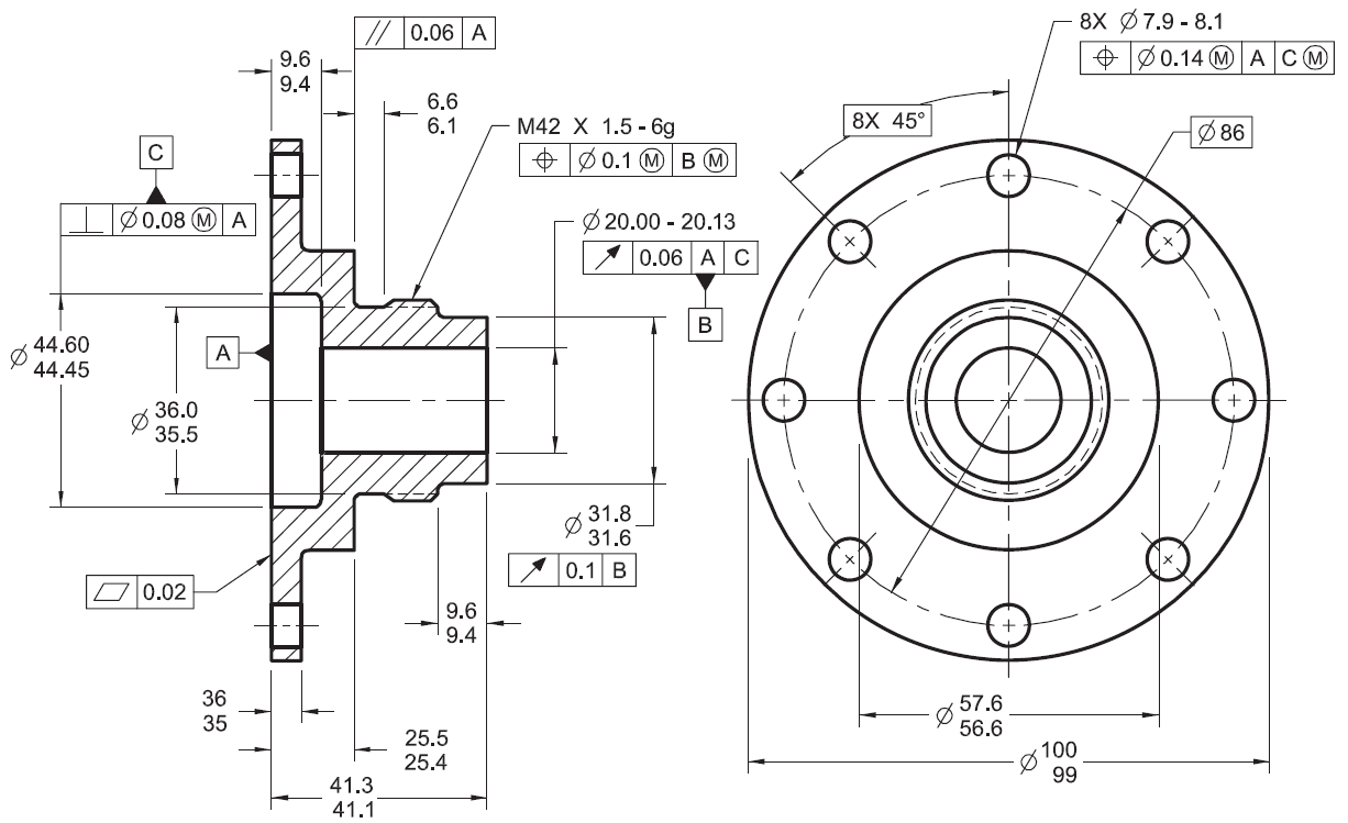
Gd&T Sample Drawing
Gd&T Sample Drawing - Here is the summary of the key gd & t symbols used in engineering drawings. Gd&t is a way of specifying engineering design and drawing requirements with particular attention to actual function and relationship of. Web gd&t, short for geometric dimensioning and tolerancing, is a system for defining and communicating design intent and engineering tolerances that helps engineers and manufacturers optimally control variations in manufacturing processes. True position, or just position as the asme y14.5 standard calls it, is defined as the total permissible variation that a feature can have from its “true” position. Gd&t aims to communicate the design intent in a way that the desired form, fit, function, and interchangeability of feature is conveyed on the drawings without confusion.
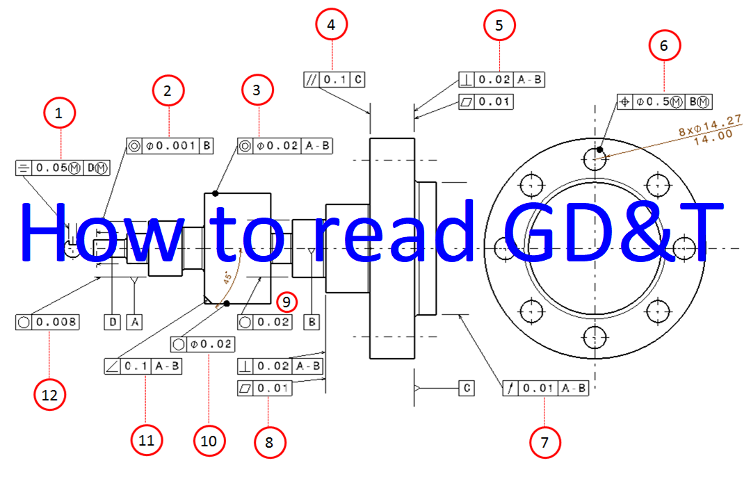
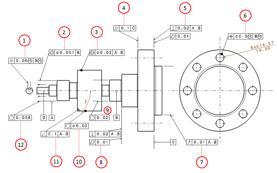
Gd&t is a way of specifying engineering design and drawing requirements with particular attention to actual function and relationship of. Gd&t is used to define the nominal (theoretically. These are grouped into symbols relating to form, profile, orientation, runout and location. International standard to specify form, fit and function of parts ansi y 14.5, iso 1101 significant improvement over traditional tolerancing focuses on 3d part geometry features in addition to 2d drawings a typical part drawing when to use gd & t ? Web gd&t drawings and symbols geometric tolerances are specified using symbols on a drawing. Currently, we have 16 symbols for geometric tolerances, which are categorized according to the tolerance they specify. And axis and surface and surface t 0.05
GD&T Drawings KOHLEX
There are numerous other optional symbols used, which we show at the end of this article. T 0.03 cylindricity (form tolerance): And axis and surface and surface t 0.05 Web what is gd & t ? The mmc and lmc act like an envelope, therefore a feature of size inherently has form control. Web the.

GD&T Blog Geometric Learning Systems
Web gd&t allows for comprehensive and consistent tolerances with the use of relatively simple tools. Web gd&t drawings and symbols geometric tolerances are specified using symbols on a drawing. Web common gd&t symbols are listed in the table below. Currently, we have 16 symbols for geometric tolerances, which are categorized according to the tolerance they.

GD&T Basics What You Need to Know
There are numerous other optional symbols used, which we show at the end of this article. History of gd&t how did. “the form of an individual regular feature of size is controlled by its limits of size”. These are grouped into symbols relating to form, profile, orientation, runout and location. Web gd&t drawings and symbols.

GD&T Tips Profile As a General Tolerance
In some cases, different terms may refer to the same concept (e.g. How to measure straightness flatness the flatness requirement specifies the evenness of a surface, or how accurately flat a target plane should be. True position theory (size value in rectangular frame) classification and symbols of geometric tolerance characteristics The mmc and lmc act.

GD&T for beginners step by step approach to do gd&t for mechanical
Web gd&t allows for comprehensive and consistent tolerances with the use of relatively simple tools. The following slides contain some errors. If it is called out on a curved surface, like a fillet on a welded part, the entire surface where the radius is has to fall within the tolerance zone. Part features are critical.
Examples on how to interpret GD&T Form, orientation, location and run
These are grouped into symbols relating to form, profile, orientation, runout and location. Parts manufactured in a shop must meet specific design requirements shown on engineering drawings. “the form of an individual regular feature of size is controlled by its limits of size”. Gd&t is a way of specifying engineering design and drawing requirements with.
GD&T Tips Directly Toleranced Dimensions
“the form of an individual regular feature of size is controlled by its limits of size”. Parts manufactured in a shop must meet specific design requirements shown on engineering drawings. Currently, we have 16 symbols for geometric tolerances, which are categorized according to the tolerance they specify. True position theory (size value in rectangular frame).

Are You Using GD&T Correctly? Geometric Learning Systems
In some cases, different terms may refer to the same concept (e.g. Engineering drawing and design by d. Form control can be additionally refined via ¶ ̧31o. “the form of an individual regular feature of size is controlled by its limits of size”. Part features are critical to function or interchangeability Review the slides use.

What are geometric dimensioning and tolerancing gd t symbols Artofit
In some cases, different terms may refer to the same concept (e.g. And axis and surface and surface t 0.05 Representative of mating features 2. This course will teach you the basics of how to understand gd&t symbols and their use. As with all new systems, there is a learning curve with gd&t. Engineering drawing.
Examples on how to interpret GD&T Form, orientation, location and run
Gd&t is a way of specifying engineering design and drawing requirements with particular attention to actual function and relationship of. These are grouped into symbols relating to form, profile, orientation, runout and location. Web common gd&t symbols are listed in the table below. Web simple steps towards a correct & complete g d & t.
Gd&T Sample Drawing This course will teach you the basics of how to understand gd&t symbols and their use. History of gd&t how did. The mmc and lmc act like an envelope, therefore a feature of size inherently has form control. Web what is gd & t ? The “ true position” is the exact coordinate, or location defined by basic dimensions or other means that represents the nominal value.
Before The Development Of Gd&T, Traditional Engineering Drawings Often Contained Many Handwritten Notes To Capture The Designers.
Part features are critical to function or interchangeability Geometric dimensioning and tolerancing, by d. Web the questions will reveal your understanding of where key information is found on a drawing, gd&t symbols and application of form tolerances, datums and how they control degrees of freedom, and much more. A part drawing may include a single gd&t callout, or the drawing may be fully defined using gd&t depending on part requirements.
The Following Slides Contain Some Errors.
Parts manufactured in a shop must meet specific design requirements shown on engineering drawings. Using gd&t results in a more accurate design, larger tolerances for less important design features, and cost savings for manufacturing. In some cases, different terms may refer to the same concept (e.g. There are numerous other optional symbols used, which we show at the end of this article.
Web Fundamentals Of Engineering Drawings And Gd&T.
True position theory (size value in rectangular frame) classification and symbols of geometric tolerance characteristics Review the slides use your reference material to find the errors example 1: And axis and surface and surface t 0.05 Web gd&t is a particular set of conventions used on engineering drawings (often called “prints” from the older “blueprints”) that communicate how parts should fit together and how they function.
Form Control Can Be Additionally Refined Via ¶ ̧31O.
Gd&t is a way of specifying engineering design and drawing requirements with particular attention to actual function and relationship of. You’ll receive your score immediately after completing the quiz. Web gd&t drawings and symbols geometric tolerances are specified using symbols on a drawing. How to measure straightness flatness the flatness requirement specifies the evenness of a surface, or how accurately flat a target plane should be.