
How To Draw A Nyquist Plot
How To Draw A Nyquist Plot - Procedure to draw nyquist plot: R = wemodify the nyquist contour. Re g(s) in a new plane, call it c4 for closed loop stability, c4 should encircle ( 1=k; The pole/zero diagram determines the gross structure of the transfer function. If we detour to the left, then the poles count as unstable open loop poles.
Procedure to draw nyquist plot: Web a nyquist plot can be drawn using the following steps: If we detour to the left, then the poles count as unstable open loop poles. Can detour to the right or left. Gopal’s method states that you only need 4 points to be able to sketch the nyquist plot, and these points are [1],[2]: The nyquist plot can provide some information about the shape of the transfer function. And this is what it should look like:
nyquist diagram tracer diagramme de nyquist Empiretory
The nyquist plot can provide some information about the shape of the transfer function. How to draw nyquist plots biomechatronics lab 3.77k subscribers subscribe 2.9k views 2 years ago nyquist stability criterion mece3350 control systems lecture 19:. This is what i get with desmos: Web control systems lecture 19: The range of gains over which.
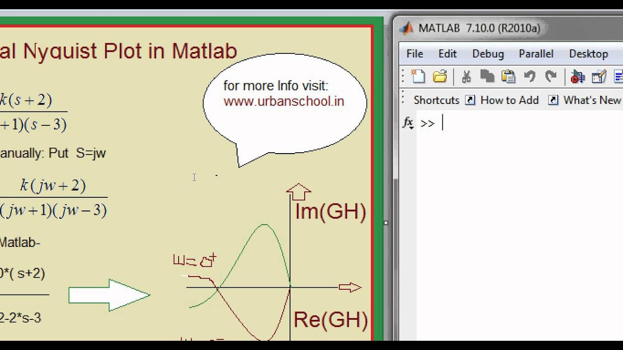
Matlab Basics Tutorial13 How to draw Nyquist plot of Transfer
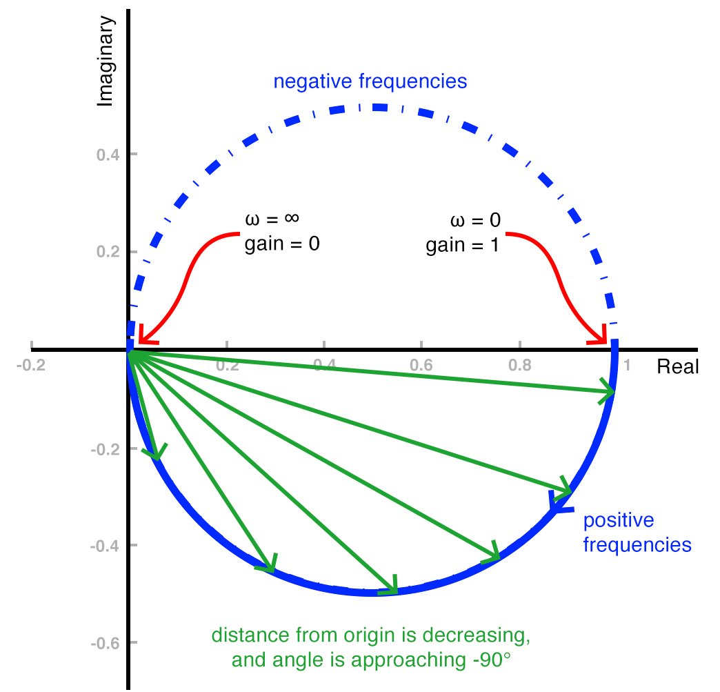
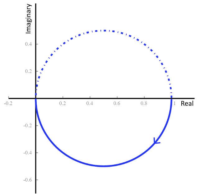
Locate the poles and zeros of open loop transfer function $g(s)h(s)$ in ‘s’ plane. And this is what it should look like: In particular, focus on the crossings of the real and imaginary axis, say the phases 0 ∘, 90 ∘, 180 ∘, 270 ∘, etc. The plot also shows arrows to indicate the direction.
Drawing Nyquist Plot at Explore collection of
The pole/zero diagram determines the gross structure of the transfer function. Procedure to draw nyquist plot: Web the key for sketching the nyquist plot is to focus on the phase and not on the magnitude. In particular, focus on the crossings of the real and imaginary axis, say the phases 0 ∘, 90 ∘, 180.

Stepbystep Nyquist plot example. Part II Fundamentals of Linear
Follow these rules for plotting the nyquist plots. If we detour to the left, then the poles count as unstable open loop poles. The range of gains over which the system will be stable can be determined by looking at crossings of the real axis. The nyquist contour passes through a pole. Web nyquist(sys) creates.
Tutorial 6How to interpret a Nyquist plot YouTube
Because of the pole, the argument principle is invalid. 0 ∘ and − 90 ∘. Web im(ω) = −re(ω) × rc 1 + (re(ω)rc)2 i m ( ω) = − r e ( ω) × r c 1 + ( r e ( ω) r c) 2 ? How do i obtain the correct plot.
How to Use a Nyquist Plot for AC Analysis Technical Articles
Nyquist plots a contour comprised of both positive and negative frequencies. The pole/zero diagram determines the gross structure of the transfer function. Web bode and nyquist plots the system or transfer function determines the frequency response of a system, which can be visualized using bode plots and nyquist plots. Because of the pole, the argument.

Stepbystep Nyquist plot example. Part III Fundamentals of Linear
In the above example, there is only two relevant angles that we need to pay attention to: Calculate the complex transfer function value by putting s= j ω, where ‘ ω’ is angular frequency and ‘j’ is the imaginary unit. And this is what it should look like: 0 ∘ and − 90 ∘. Web.

How to draw the Nyquist plot Example No. 2 for TypeOne System Simple
Web im(ω) = −re(ω) × rc 1 + (re(ω)rc)2 i m ( ω) = − r e ( ω) × r c 1 + ( r e ( ω) r c) 2 ? Gopal’s method states that you only need 4 points to be able to sketch the nyquist plot, and these points are [1],[2]:.

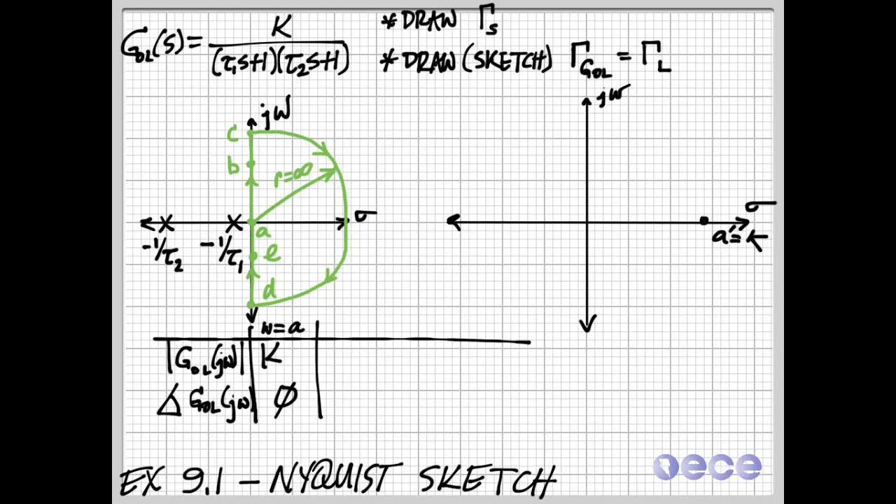
Nyquist Sketch Example YouTube
Web note that if p is nonzero, then the nyquist plot must encircle the point 1 k p times in a counterclockwise direction (e.g. Web the nyquist plot problem: In the above example, there is only two relevant angles that we need to pay attention to: Locate the poles and zeros of open loop transfer.

Sample Nyquist plot illustrating a situation when gain margin and phase
The pole/zero diagram determines the gross structure of the transfer function. If we detour to the left, then the poles count as unstable open loop poles. The nyquist contour passes through a pole. Because of the pole, the argument principle is invalid. Web control systems lecture 19: G ( s) = s + 2 s.
How To Draw A Nyquist Plot Web im(ω) = −re(ω) × rc 1 + (re(ω)rc)2 i m ( ω) = − r e ( ω) × r c 1 + ( r e ( ω) r c) 2 ? Draw and map using nyquist contour rules of nyquist plot. How do i obtain the correct plot using standard function plotting techniques? Web in general each example has five sections: If pole or zero present at s = 0, then varying $\omega$ from 0+ to infinity for drawing polar plot.
Web Tutorialspoint 5 Years Ago Bode Plot Example 13 Videos Bode Plot Engineering Funda Nyquist Plot Example 2, Procedure To Draw Nyquist Plot In Control Engineering By Engineering Funda.
Calculate the complex transfer function value by putting s= j ω, where ‘ ω’ is angular frequency and ‘j’ is the imaginary unit. If pole or zero present at s = 0, then varying $\omega$ from 0+ to infinity for drawing polar plot. The pole/zero diagram determines the gross structure of the transfer function. In particular, focus on the crossings of the real and imaginary axis, say the phases 0 ∘, 90 ∘, 180 ∘, 270 ∘, etc.
The Plot Displays Real And Imaginary Parts Of The System Response As A Function Of Frequency.
Draw inverse polar plot 3. Web rules for drawing nyquist plots. Web stability is determined by looking at the number of encirclements of the point (−1, 0). 0 ∘ and − 90 ∘.
The Plot Also Shows Arrows To Indicate The Direction Of Increasing Frequency For.
And this is what it should look like: Web note that if p is nonzero, then the nyquist plot must encircle the point 1 k p times in a counterclockwise direction (e.g. Follow these rules for plotting the nyquist plots. In this video, i have explained nyquist plot example and nyquist plot procedure with following.
I Tried That, But The Result In Desmos Isn't Similar To The Nyquist Plot Generated Using Matlab Or Maple.
Because of the pole, the argument principle is invalid. Web the nyquist plot problem: In the above example, there is only two relevant angles that we need to pay attention to: If we detour to the left, then the poles count as unstable open loop poles.