
How To Read Pipe Drawings
How To Read Pipe Drawings - These tools generate the 3d representation of the piping layout, including pipe dimensions, fittings,. This video is about how to read basic piping isometric drawing for isometric symbols. Web piping and instrumentation diagrams (p&ids) use specific symbols to show the connectivity of equipment, sensors, and valves in a control system. Pipe routing, length, and coordinates. The connection types from the controllers to the field devices.
The isometrics drawing are created. Methodology of drawing pipeline isometric drawings. Web tutorial piping tips and tricks. Web how to read isometric drawing in a piping isometrics drawing, pipe is drawn according to it’s length, width and depth, and often shown in a single view. Each pipe will be coded and included in the isometric drawings. Web importance of engineering drawing. The drawing axes of the isometrics intersect at an angle of 60°.

How to read isometric piping drawing in English YouTube
Web to read piping isometric drawing you must know the following things: Sample piping ga drawing a piping plan drawing provides the following necessary information: Web how to read a piping isometric? Spacing or centreline distance between one pipe to the other line. It is 2d drawings that represent the. Web this course provides 2.
Instrumentation Today HOW TO READ AN ISOMETRIC PIPING DRAWING
Web tutorial piping tips and tricks. Reading or tracing a p&id drawing to understand the process or design requirements are quite easy if the p&id symbols are properly understood. Web make a p&id what is p&id? Methodology of drawing pipeline isometric drawings. Web how to fabricate a piping spool explained for fitters, and fabricators. Type.

How to read piping Isometric drawing YouTube
Correct positioning of the piping assembly on the pipe rack. Web piping and instrumentation diagrams (p&ids) use specific symbols to show the connectivity of equipment, sensors, and valves in a control system. Type of pipe supports required in the piping and pipeline systems. Web how to fabricate a piping spool explained for fitters, and fabricators..

How to read piping isometric drawing pdf fleetlio
Web make a p&id what is p&id? Web how to read p&id drawings? Reading a piping isometric drawing basic training. The p&id diagram tells us where the device is located exactly. The connection types from the controllers to the field devices. Web to read piping isometric drawing you must know the following things: Web how.

Piping Design Basics Piping Isometric Drawings Piping Isometrics
Reading or tracing a p&id drawing to understand the process or design requirements are quite easy if the p&id symbols are properly understood. Web make a p&id what is p&id? Each pipe will be coded and included in the isometric drawings. Sample piping ga drawing a piping plan drawing provides the following necessary information: Web.
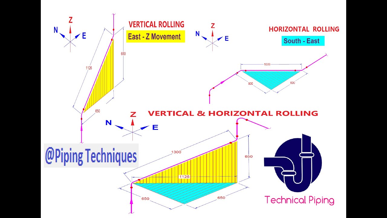
PipingHow to Read Pipe Rolling/Offset in Isometric Drawing? YouTube
These tools generate the 3d representation of the piping layout, including pipe dimensions, fittings,. So, not from the outside of a pipe or fitting. Piping isometric drawing dimensions are always from center to center of pipe. The isometrics drawing are created. Pipe routing, length, and coordinates. The connection types from the controllers to the field.

How to Read Basic Piping Isometric Drawings Piping Analysis YouTube
Reading or tracing a p&id drawing to understand the process or design requirements are quite easy if the p&id symbols are properly understood. Web how to read a piping isometric? These symbols can represent actuators, sensors, and controllers and may be apparent in most, if not all, system diagrams. Web tutorial piping tips and tricks..
Learn isometric drawings (piping isometric)
The device tag in p&id is represented by a circle followed by tag numbers such as fv304. Web i̇n this video we will learn piping, how to read pipe drawing, bending wire for pipe isometry, pipe size, 10 inch pipe size, 10 pipe outside diameter, 10 pipe, pipe outside. Web this course provides 2 days.
How to read piping isometric drawing plmservers
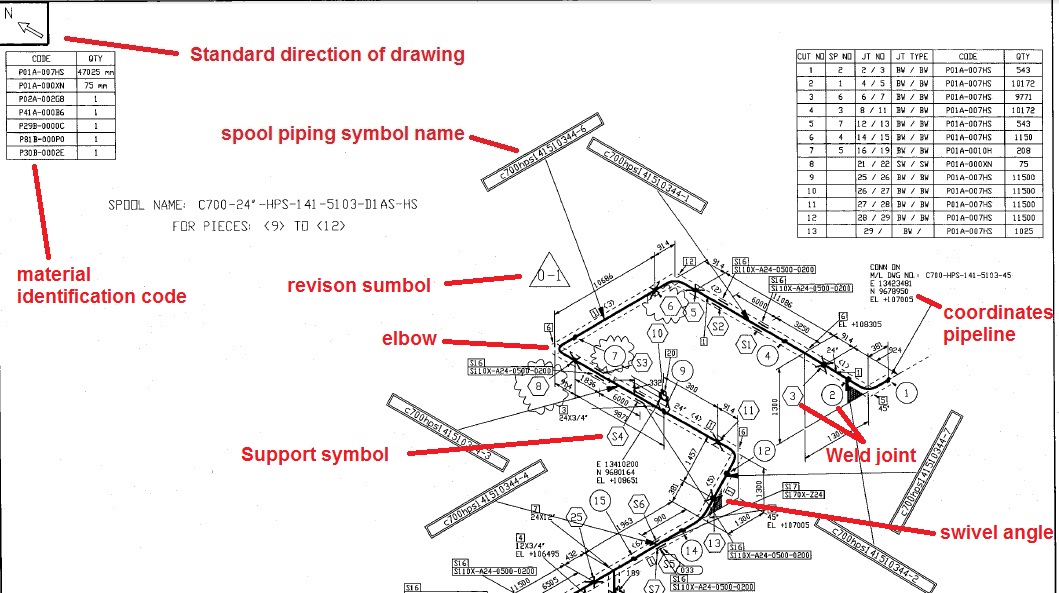
Familiarize yourself with these symbols for better comprehension. Web technical piping 128k subscribers join subscribe 419 share save 22k views 4 years ago reading isometric drawing this video explain about piping isometric drawing details 1.how to read. Sample piping ga drawing a piping plan drawing provides the following necessary information: Web use of piping symbols:.

How to read piping isometric drawing, Pipe fitter training, Watch the
The device tag in p&id is represented by a circle followed by tag numbers such as fv304. The p&id diagram tells us where the device is located exactly. Classes are offered in these formats: These tools generate the 3d representation of the piping layout, including pipe dimensions, fittings,. It’s most commonly used in the engineering.
How To Read Pipe Drawings Familiarize yourself with these symbols for better comprehension. Each pipe will be coded and included in the isometric drawings. The image below shows a orthographic view of a butt welded pipe with three sizes (a, b, c). Piping isometric symbols and conventions are employed to depict different components of pipeline systems, such as valves, fittings, and connections. Type of pipe supports required in the piping and pipeline systems.
Pipe Size Is Always Written At Any Connecting Point Of Isometric.
Web tag numbers on a p&id are a series of letters followed by numbers that are used to identify a device type and its function being used for a particular process or a control loop. Piping isometric drawing dimensions are always from center to center of pipe. Web piping isometric drawing software is an essential tool for piping engineers and designers to create detailed isometric drawings of piping systems. Spacing or centreline distance between one pipe to the other line.
Isometric Views Can Be Identified By Their Characteristic Lines And Angles.
So, not from the outside of a pipe or fitting. Web tutorial piping tips and tricks. Pipe routing, length, and coordinates. Type of pipe supports required in the piping and pipeline systems.
P&Ids Provide More Detail Than A Process Flow Diagram With The Exception Of.
Web how to fabricate a piping spool explained for fitters, and fabricators. This single line is the centerline of the pipe, and from that line, the dimensions measured. It is 2d drawings that represent the. Each pipe will be coded and included in the isometric drawings.
A Piping And Instrumentation Diagram, Or P&Id, Shows The Piping And Related Components Of A Physical Process Flow.
Web a piping isometric drawing is a technical drawing that depicts a pipe spool or a complete pipeline using an isometric representation. In the example at left, note that all directions of the pipe match the three isometric axis lines scale: 144k views 5 years ago piping isometric. A pipe into a isometric view, is always drawn by a single line.