
Hydraulic Schematic Drawing
Hydraulic Schematic Drawing - How filters are selected 40. In a hydraulic schematic, each line type has a unique meaning. A hydraulic schematic also indicates the types and capabilities of components in the circuit. Web basic diagrams & systems graphic symbols for fluid power diagrams basic diagrams and systems in the preceding chapters, you learned about hydraulic and pneumatic fluids and components of fluid power systems. Hydraulic symbols are neither dimensioned nor specified for any particular position.
If you want to create a pneumatic drawing, use the insert pneumatic components tool on the schematic tab insert components panel. Basic hydraulic circuits use strategic placement of control valves and components to manipulate fluid and achieve specific results. Our free trial gives you access to a fully functional hydrosym. Web hydraulic mid inlets 29. Web basic diagrams & systems graphic symbols for fluid power diagrams basic diagrams and systems in the preceding chapters, you learned about hydraulic and pneumatic fluids and components of fluid power systems. Web create a pneumatic or hydraulic control system diagram in visio 2016 and newer versions: Symbols for hydraulic systems are for functional interpretation and comprise one or more function symbols.

Simple Hydraulic Circuit Drawing Merge Wiring
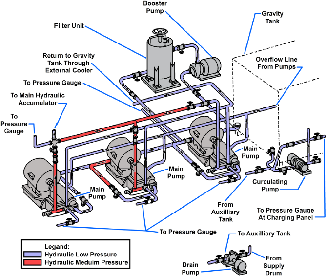
In the figure below, all of the basic line types are shown. Intake water pressure is monitored by pressure gauge (3). Drag equipment and valve shapes onto the drawing page. Smartdraw's schematic diagram software is easy to use. Web on this page, carr lane roemheld provides a comprehensive table outlining the definitions of each symbol.
How To Read Hydraulic Circuit Diagrams
Hydraulic symbols are neither dimensioned nor specified for any particular position. Click templates > engineering > fluid power > create. Web hydraulics schematic symbols are a basic component of hydraulic circuit. Web the complexity of these components are difficult to represent fully, so a family of graphic symbols have been developed to represent fluid power.

Simple Hydraulic Circuit Drawing Merge Wiring
Select from a huge library of vector schematic diagram symbols that scale easily without quality degradation. Draw the schematic symbol for a double acting hydraulic cylinder, a hydraulically extended spring retracted single acting cylinder, a spring extended hydraulically retracted single acting cylinder, and single acting ram. This will make it much easier to interpret the.
Basic Hydraulic Schematic Diagram
Request your trial and start drawing your first diagram in 15 minutes! Intake water pressure is monitored by pressure gauge (3). Web create a pneumatic or hydraulic control system diagram in visio 2016 and newer versions: Web on this page, carr lane roemheld provides a comprehensive table outlining the definitions of each symbol used in.
Basic Diagrams and Systems Engineering Library
Select from a huge library of vector schematic diagram symbols that scale easily without quality degradation. This will make it much easier to interpret the schematic. Web in this lesson we'll review schematic symbols for common fluid power devices including fluid conductors, prime movers, pumps, reservoirs, actuators, directio. It includes thousands of templates and examples.

Hydraulic System Schematic
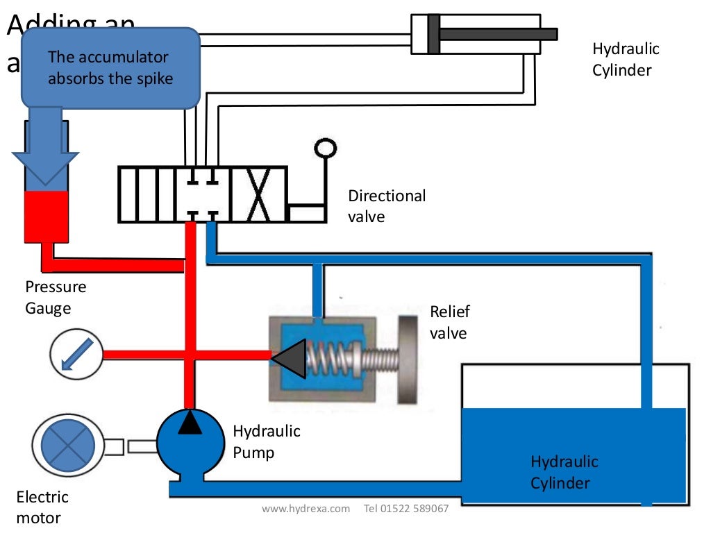
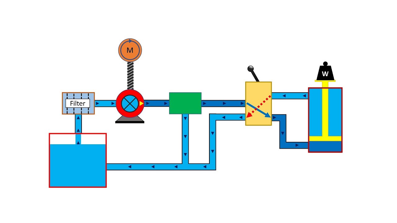
Web a hydraulic schematic diagram uses lines and symbols to provide a visual display of fluid paths within a hydraulic circuit. Basic hydraulic circuits use strategic placement of control valves and components to manipulate fluid and achieve specific results. Next, pay attention to the arrows. The following list is contains hydraulic schematic symbols to din.

The hydraulic circuit diagram of a plant with two actuators. Download
If you want to create a pneumatic drawing, use the insert pneumatic components tool on the schematic tab insert components panel. Request your trial and start drawing your first diagram in 15 minutes! Web define a hydraulic cylinder. Web hydraulics schematic symbols are a basic component of hydraulic circuit. Basic hydraulic circuits use strategic placement.

HYDRAULIC SYSTEM FOR BEGINNERS Mechanical Engineering Professionals
A simple hydraulic schematic showing apparatus for testing the strength of a hydraulic hose splice. Draw the schematic symbol for a double acting hydraulic cylinder, a hydraulically extended spring retracted single acting cylinder, a spring extended hydraulically retracted single acting cylinder, and single acting ram. If you want to create a pneumatic drawing, use the.
Hydraulic Symbols and Schematic For Beginners How to Read Hydraulic
This will make it much easier to interpret the schematic. If you want to create a pneumatic drawing, use the insert pneumatic components tool on the schematic tab insert components panel. Hydrosym will enable you to quickly and easily design a wide range of hydraulic systems, from a small power unit to a large hydraulic.

Simple Hydraulic Circuit Drawing Merge Wiring
Web create schematics for your hydraulic system in no time. Intake water pressure is monitored by pressure gauge (3). Single acting double acting cylinders 35. In addition, colors can be added to indicate purpose of the line. The basic line is a solid line that represents a working pressure hose or tube. Web on this.
Hydraulic Schematic Drawing Request your trial and start drawing your first diagram in 15 minutes! In the figure below, all of the basic line types are shown. Web hydraulic p&id diagrams and schematics, hydraulic piping, hydraulic diagrams, hydraulic symbols, hydraulic line diagrams, pneumatic p&id, pneumatic symbols. Intake water pressure is monitored by pressure gauge (3). Our free trial gives you access to a fully functional hydrosym.
Familiarize Yourself With These Symbols By Consulting Books Or Manuals That Describe What Each Symbol Stands For.
Yes, this includes our unlimited. Web the complexity of these components are difficult to represent fully, so a family of graphic symbols have been developed to represent fluid power components and systems on schematic drawings. If you want to create a pneumatic drawing, use the insert pneumatic components tool on the schematic tab insert components panel. Select from a huge library of vector schematic diagram symbols that scale easily without quality degradation.
Symbols For Hydraulic Systems Are For Functional Interpretation And Comprise One Or More Function Symbols.
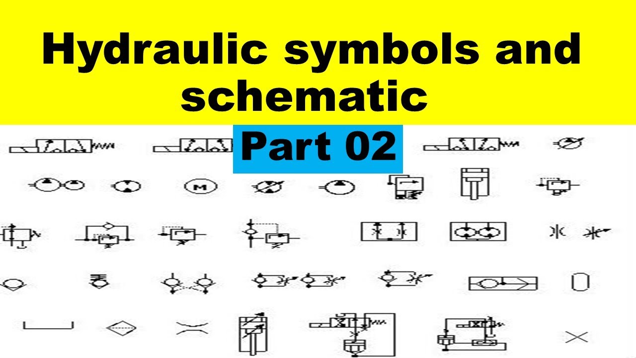
Sign up for a free 30 days trial now! Web on this page, carr lane roemheld provides a comprehensive table outlining the definitions of each symbol used in a hydraulic diagram. A simple hydraulic schematic showing apparatus for testing the strength of a hydraulic hose splice. Web in this video we talk about the schematic component symbols for a hydraulic pump, electric motor, various filters and heat exchangers, and a bunch of components associated with the hydraulic.
Web Hydraulics Schematic Symbols Are A Basic Component Of Hydraulic Circuit.
In addition, colors can be added to indicate purpose of the line. Web hydraulic schematics use a wide range of symbols to represent different parts and connections. Web in this lesson we'll review schematic symbols for common fluid power devices including fluid conductors, prime movers, pumps, reservoirs, actuators, directio. In a hydraulic schematic, each line type has a unique meaning.
Water Enters Through Normally Closed Solenoid Valve (1) And Passes Through Intake Flow Meter (2) To High Pressure Pump (4).
Basic hydraulic circuits use strategic placement of control valves and components to manipulate fluid and achieve specific results. Web create schematics for your hydraulic system in no time. This will make it much easier to interpret the schematic. The following list is contains hydraulic schematic symbols to din iso 1219.