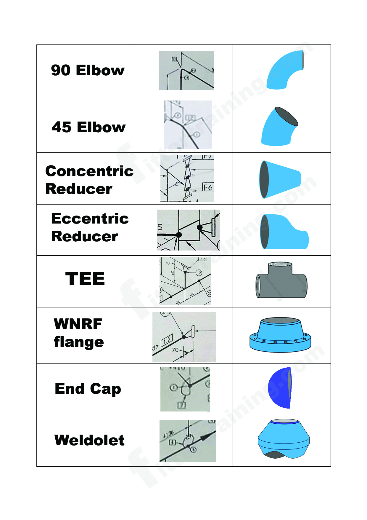
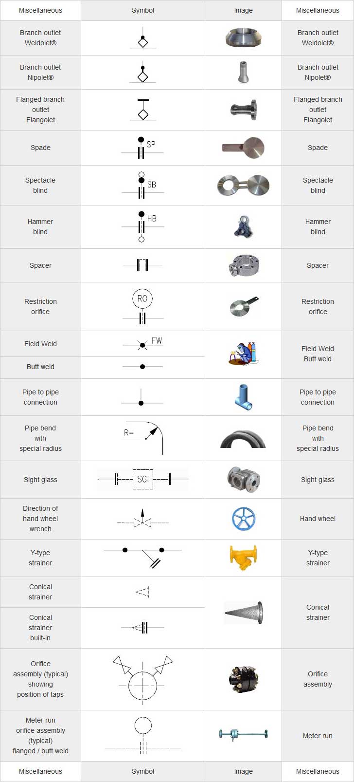
Isometric Pipe Drawing Symbols
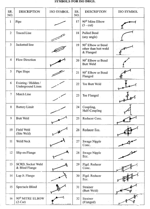
Isometric Pipe Drawing Symbols - Web symbols for piping and instrumentation diagrams (pid). Familiarize yourself with these symbols for better comprehension. Pipes are shown as single lines, and symbols are used to represent pipe fittings, valves, pipe gradients, and welds. Example of rolling angle calculation: The symbols that represent fittings, valves and flanges are modified to adapt to the isometric grid.
Web the isometrics drawing are created from information found on a plan and elevation views. By using this information and the isometric symbols that correspond to the various orthographic drawing symbols the pipe drafter can render an isometric describing the pipe's routing. Isometrics are usually drawn from information found on a plan and elevation views. Pipes are shown as single lines, and symbols are used to represent pipe fittings, valves, pipe gradients, and welds. Lighter lines show connected pipe, and are not parts of the symbols. Example of rolling angle calculation: It’s popular within the process piping industry because it can be laid out and drawn with ease and portrays the object in a.
How to read isometric drawing piping dadver
This comprehensive block library organizes all of. Lighter lines show connected pipe, and are not parts of the symbols. Web the isometrics drawing are created from information found on a plan and elevation views. Although the pipeline is accurately dimensioned, it is deliberately not drawn to scale and therefore does not correspond exactly to a.
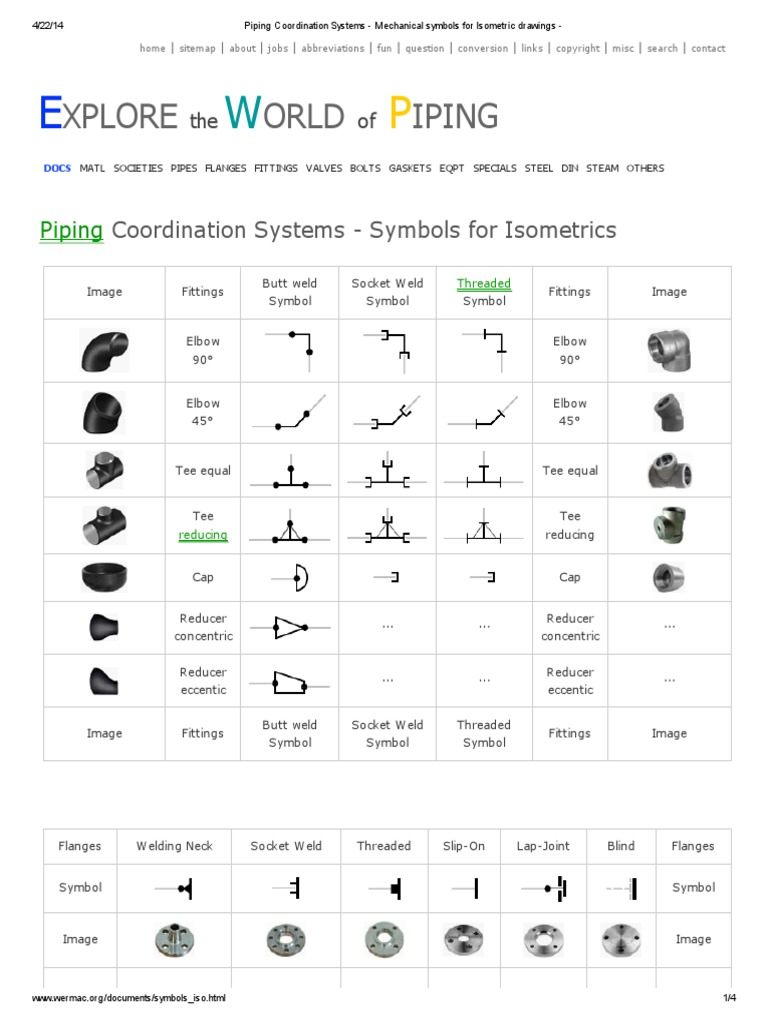
Piping Coordination Systems Mechanical symbols for Isometric drawings
User friendly interface with a couple clicks of the mouse, you'll be able to quickly insert the symbol you need to generate isometric piping drawings with ease. Web the isometrics drawing are created from information found on a plan and elevation views. It’s popular within the process piping industry because it can be laid out.
Piping Isometric Drawings The Piping Engineering World
Web isometric drawing symbols for valves buttweld ball valve buttweld butterfly valve buttweld check valve buttweld gate valve buttweld globe valve buttweld needle valve buttweld plug valve buttweld three way valve buttweld y type valve flanged ball valve flanged bottom valve flanged butterfly valve flanged check valve flanged diaphragm. Web accurate drawing symbols, callouts, precise.
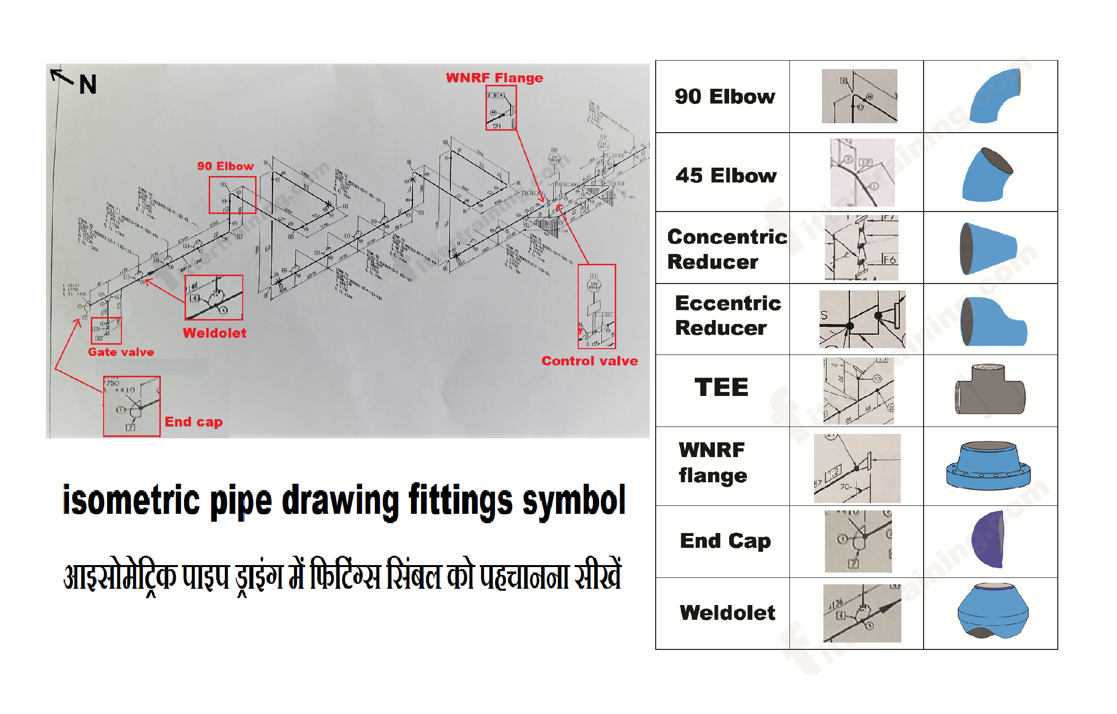
isometric pipe drawing fittings symbol Fitter training
Symbols are shown in black lines. Web symbols for piping and instrumentation diagrams (pid). It’s popular within the process piping industry because it can be laid out and drawn with ease and portrays the object in a. Web this video shows isometric drawing symbols for various types of valves such as gate valves, globe valves,.
Piping Isometric Drawing Symbols Pdf at Explore
Conclusion what is piping isometric drawing? It’s popular within the process piping industry because it can be laid out and drawn with ease and portrays the object in a. Symbols like fittings, valves and flanges are modified to adapt to the isometric grid. Web drawing symbols, callouts, coordinates, and elevations provide detailed information of the.
isometric pipe drawing fittings symbol Fitter training
Various symbols are used to indicate piping components, instrumentation, equipments in engineering drawings such as piping and instrumentation diagram (p&id), isometric drawings, plot plan, equipment layout, welding drawings etc. Isometrics are usually drawn from information found on a plan and elevation views. Web coordination system symbols for isometrics pipe drawings are much different from specific.
PIPE FITTING ISOMETRIC Free CAD Block Symbols And CAD Drawing
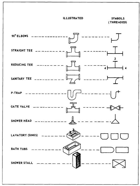
Web use of piping symbols: Web piping isometric drawing software is an essential tool for piping engineers and designers to create detailed isometric drawings of piping systems. Piping isometric symbols and conventions are employed to depict different components of pipeline systems, such as valves, fittings, and connections. Isometric symbols corresponding to their orthographic equivalents help.
What is Piping Isometric drawing? How to Read Piping Drawing? ALL
Web the isometrics drawing are created from information found on a plan and elevation views. Web coordination system symbols for isometrics pipe drawings are much different from specific weld symbols but they do have a similar relationship from part to symbol. Isometrics are usually drawn from information found on a plan and elevation views. Web.
Piping Coordination System Mechanical symbols for Isometric drawings
Web this video shows isometric drawing symbols for various types of valves such as gate valves, globe valves, check valves, butterfly valves, diaphragm valves, ball valves, angle valves, y type valves. Web the isometrics drawing are created from information found on a plan and elevation views. Symbols like fittings, valves and flanges are modified to.
Basic Piping Isometric Symbols Piping Analysis YouTube
This comprehensive block library organizes all of. Are tagged with the same codes used on the p&id and ga. Although the pipeline is accurately dimensioned, it is deliberately not drawn to scale and therefore does not correspond exactly to a real. Some individuals will not see these in their line. Web isometric drawing symbols for.
Isometric Pipe Drawing Symbols Web isometric drawing symbols for valves buttweld ball valve buttweld butterfly valve buttweld check valve buttweld gate valve buttweld globe valve buttweld needle valve buttweld plug valve buttweld three way valve buttweld y type valve flanged ball valve flanged bottom valve flanged butterfly valve flanged check valve flanged diaphragm. Isometric views can be identified by their characteristic lines and angles. It’s popular within the process piping industry because it can be laid out and drawn with ease and portrays the object in a. Pipes are shown as single lines, and symbols are used to represent pipe fittings, valves, pipe gradients, and welds. Piping isometric symbols and conventions are employed to depict different components of pipeline systems, such as valves, fittings, and connections.
How To Read Piping Isometric Drawing Symbols.
Web the isometrics drawing are created from information found on a plan and elevation views. By using this information and the isometric symbols that correspond to the various orthographic drawing symbols the pipe drafter can render an isometric describing the pipe's routing. Web coordination system symbols for isometrics pipe drawings are much different from specific weld symbols but they do have a similar relationship from part to symbol. Pipes are shown as single lines, and symbols are used to represent pipe fittings, valves, pipe gradients, and welds.
Web Isometric Piping Drawings Are Not Scale Drawings, So They Are Dimensioned.
Web an isometric drawing is a type of pictorial drawing in which three sides of an object can be seen in one view. Web accurate drawing symbols, callouts, precise coordinates, and elevations provide intricate information to the fabricator. Symbols like fittings, valves and flanges are modified to adapt to the isometric grid. Web use of piping symbols:
Unlike Orthographics, Piping Isometrics Allow The Pipe To Be Drawn In A Manner By Which The Length, Width And Depth Are Shown In A Single View.
Although the pipeline is accurately dimensioned, it is deliberately not drawn to scale and therefore does not correspond exactly to a real. The symbols that represent fittings, valves and flanges are modified to adapt to the isometric grid. The drawing axes of the isometrics intersect at an angle of 60°. Web drawing symbols, callouts, coordinates, and elevations provide detailed information of the pipe's configuration and routing through the unit.
Familiarize Yourself With These Symbols For Better Comprehension.
Lighter lines show connected pipe, and are not parts of the symbols. Isometrics are usually drawn from information found on a plan and elevation views. Are tagged with the same codes used on the p&id and ga. This comprehensive block library organizes all of.


