
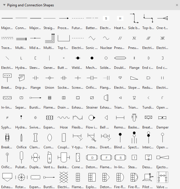
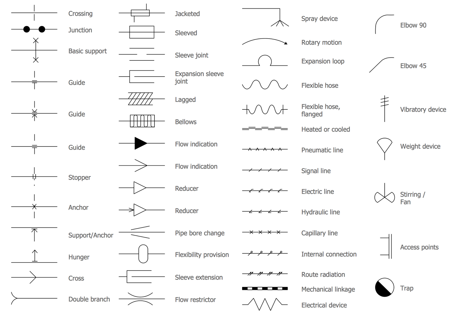
Piping Drawing Symbols
Piping Drawing Symbols - Example of rolling angle calculation: Web piping and instrument diagram standard symbols detailed documentation provides a standard set of shapes & symbols for documenting p&id and pfd, including standard shapes of instrument, valves, pump, heating exchanges, mixers, crushers, vessels, compressors, filters, motors and connecting shapes. A diagram which shows the interconnection of process equipment and the instrumentation used to control the process. 1.2 this set of standard symbols is intended for use on piping system diagrammatics and arrangements for ships. It is the most important deliverable of piping engineering department.
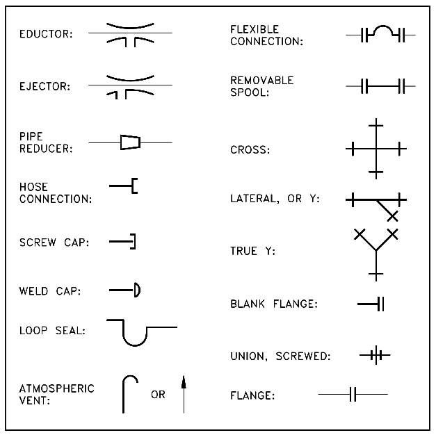
Web a piping and instrumentation diagram (p&id) is defined as follows: For example if a 90 degree elbow is to be placed in service the drawing will reflect a 90 degree angle. Piping fabrication work is based on isometric drawings. All components are represented using various p&id symbols. Piping components (pipes, flanges, and fittings) valves; Fittings are used to connect and redirect pipes. Web as with weld symbols, pipe symbols are a reflection of what that part would look like in theory.

Basic Piping Isometric Symbols Piping Analysis YouTube
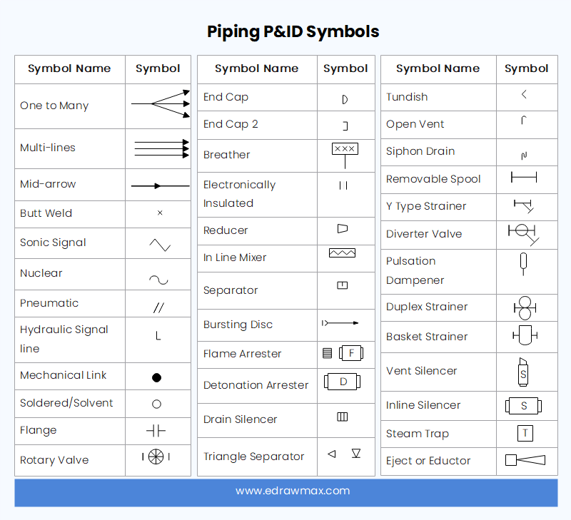
Electrical gadgets (motors, generators, and turbines) heat exchangers; Piping and instrumentation diagrams are graphical representations of a process system. Piping isometric drawing consists of three sections. P&id is an abbreviation meaning ‘ piping and instrumentation diagram ‘. Web a complete collection of the most used p&id symbols for lines, piping, valves, instruments, pumps, compressors, pressure.

Piping Isometric Drawings The Piping Engineering World
Isometric drawing piping symbols serve as a ready reference for the type of fittings and components. Web plot plan layout piping isometric drawing types of piping drawings for designing processes or power piping, mostly five types of piping drawings are developed. It is the most important deliverable of piping engineering department. These symbols can represent.

standard piping symbols Engineering Feed
Example of rolling angle calculation: Web a piping and instrumentation diagram (p&id) is defined as follows: Web to mostly colored p&id symbols exist scheduled below: In the process industry, a standard set of symbols is. The thickness and style of the lines may vary to indicate different pipe materials, sizes, or attributes. Web piping symbols,.
Piping Isometric Drawing Symbols Pdf at Explore
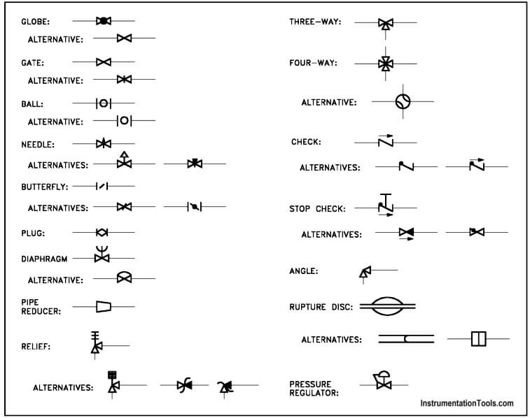
For example if a 90 degree elbow is to be placed in service the drawing will reflect a 90 degree angle. These symbols are used to indicate the type of connection, the direction of flow, and the size of the pipe. Web piping symbols for isometric drawings feature of piping drawing symbols piping symbol chart.
Piping and Instrumentation Symbols Instrumentation Tools
Conclusion what is piping isometric drawing? 1.2 this set of standard symbols is intended for use on piping system diagrammatics and arrangements for ships. These symbols are used to indicate the type of connection, the direction of flow, and the size of the pipe. It is the most important deliverable of piping engineering department. Piping.

What is Piping Isometric drawing? How to Read Piping Drawing? ALL
All components are represented using various p&id symbols. Piping components (pipes, flanges, and fittings) valves; There may be multiple symbols for one fitting or part depending on the fashion it is to be installed (butt weld, socket weld, threaded.) Common fittings include elbows, tees, reducers, and couplings. Main graphic section consist of isometric representation of.
Piping and Instrumentation Symbols Instrumentation Tools
Piping and pipeline drawing symbols throw lights on the type of joint like buttweld, socket weld, or threaded. 1.3 where graphical symbols are required for an item or equipment not covered by this practice, the form and character of the symbol. Isometric drawing piping symbols serve as a ready reference for the type of fittings.
What is a P&ID Beginner’s Guide EdrawMax Online
Users can also import svg and other image files to create a custom p&id library for any situation. A diagram which shows the interconnection of process equipment and the instrumentation used to control the process. Checkout list of such symbols given below. Web what does p&id mean? Common fittings include elbows, tees, reducers, and couplings..
Plumbing and Piping Plan Symbols Edraw
For example if a 90 degree elbow is to be placed in service the drawing will reflect a 90 degree angle. Piping fabrication work is based on isometric drawings. Web what does p&id mean? Web as with weld symbols, pipe symbols are a reflection of what that part would look like in theory. Common fittings.
Piping and Instrumentation Diagram Software
Piping fabrication work is based on isometric drawings. Example of rolling angle calculation: P&id is an abbreviation meaning ‘ piping and instrumentation diagram ‘. For example if a 90 degree elbow is to be placed in service the drawing will reflect a 90 degree angle. Users can also import svg and other image files to.
Piping Drawing Symbols Web plumbing symbols enable an architect to effectively install, locate, and fix the pipelines and plumbing tools into the building. In isometric drawings, pipes are represented as lines. These symbols are used to indicate the type of connection, the direction of flow, and the size of the pipe. Isometric drawing piping symbols serve as a ready reference for the type of fittings and components. Users can also import svg and other image files to create a custom p&id library for any situation.
These Are Fundamental To Every Standardized Engineering Project.
Checkout list of such symbols given below. P&id is an abbreviation meaning ‘ piping and instrumentation diagram ‘. Isometric drawing piping symbols serve as a ready reference for the type of fittings and components. Web knowing the piping drawing symbols will provide various information like:
Piping Fabrication Work Is Based On Isometric Drawings.
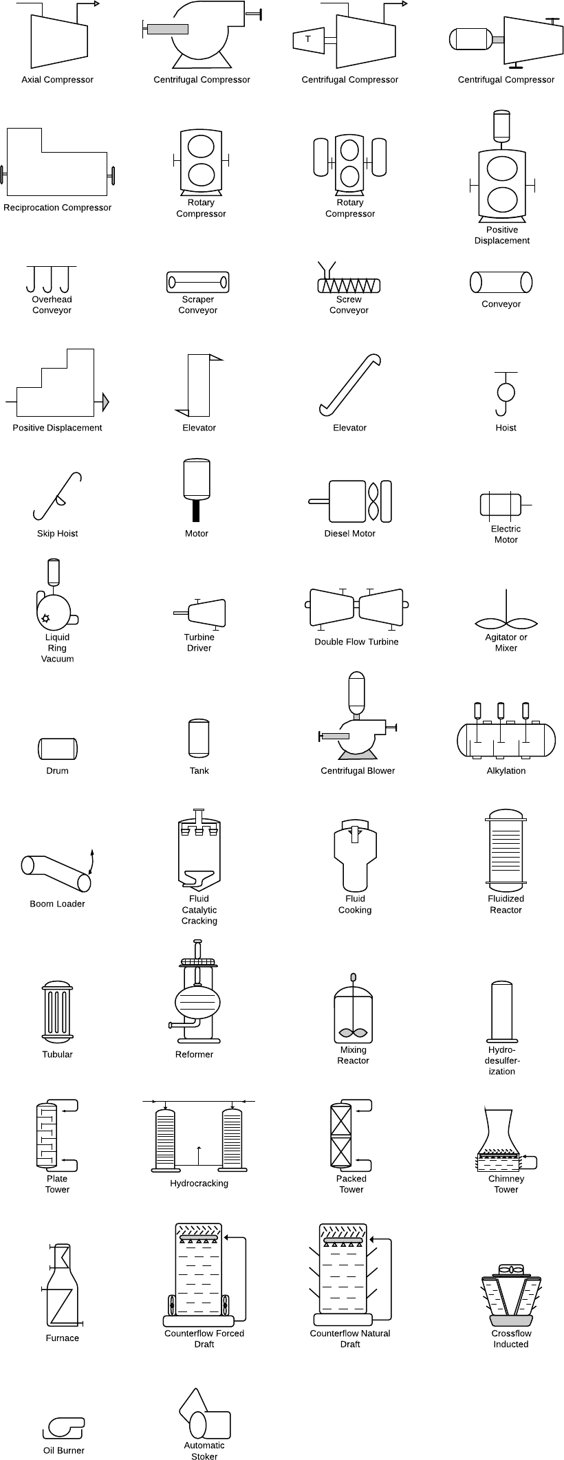
Piping components (pipes, flanges, and fittings) valves; Web plot plan layout piping isometric drawing types of piping drawings for designing processes or power piping, mostly five types of piping drawings are developed. Equipment, piping, vessels, heat exchangers, pumps, instruments, and valves. With lucidchart, it's easy to access all of the featured p&id symbols.
Fittings Are Used To Connect And Redirect Pipes.
1.2 this set of standard symbols is intended for use on piping system diagrammatics and arrangements for ships. Main graphic section consist of isometric representation of a pipe line route. For example if a 90 degree elbow is to be placed in service the drawing will reflect a 90 degree angle. These various types of piping drawings in engineering organizations are:
Piping And Pipeline Drawing Symbols Throw Lights On The Type Of Joint Like Buttweld, Socket Weld, Or Threaded.
Electrical gadgets (motors, generators, and turbines) heat exchangers; Conclusion what is piping isometric drawing? Web piping isometric drawing is an isometric representation of single pipe line in a plant. These symbols can represent actuators, sensors, and controllers and may be apparent in most, if not all, system diagrams.