
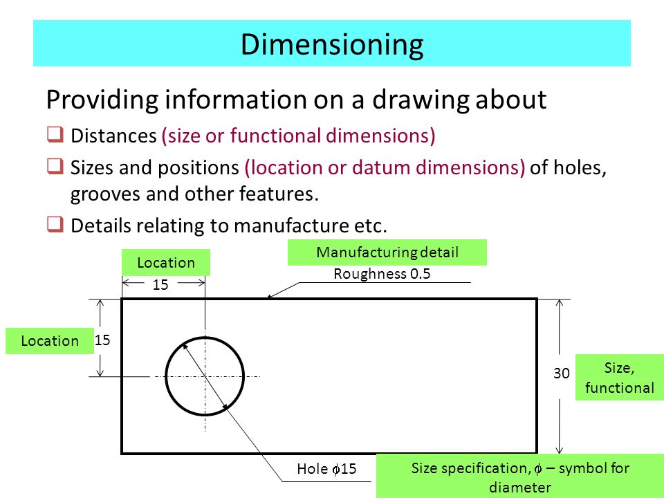
Reference Dimensions On Drawings
Reference Dimensions On Drawings - Dimensioning of part drawings 1. You can dimension to a silhouette edge. Methods and steps for dimensioning parts 3. An alternate type is at follow the dimension with “reference” or “ref”. These are called out on a drawing using parenthesis (i.e., 5.125).
To use of “ref” or enclosing the dimension inside aside are by far the most. Reference dimensions are provided for a variety of reasons and are often an accumulation of other dimensions that are defined elsewhere (e.g. You can dimension to a silhouette edge. On the drawing or other related documentation). Web how are reference dimensions shown on a drawing? The use of “ref” or enclosing the dimension inside parentheses are. These dimensions may also be used for convenience to.
Drawing Dimension Symbols at Explore collection of
In a drawing view, click the items you want to dimension. An alternate type is at follow the dimension with “reference” or “ref”. Point to the silhouette edge, and when the pointer appears, click to dimension. Web there be no gd&t symbol for a reference dimension. An alternate method are to follow the dimension with.

Drawing Dimension Symbols at Explore collection of
You can dimension to a silhouette edge. These dimensions may also be used for convenience to. Web there be no gd&t symbol for a reference dimension. Web to add a reference dimension: Use rapid dimensioning to place evenly spaced dimensions. And application by “ref” or enclosing the dimension inside clamping are by far the most.
Dimensioning on technical drawing THEME 4 Introduction
Dimensioning of part drawings 1. Web to add a reference dimension: It also could be a dimension that. And application by “ref” or enclosing the dimension inside clamping are by far the most common notations. An alternate method is to follow the dimension with “reference” or “ref”. Use rapid dimensioning to place evenly spaced dimensions..
Dimensioning on technical drawing THEME 4 Introduction
Precautions for dimensioning basic requirements for dimensioning in part drawings the dimensions in the part drawing shall be marked in accordance with the standard, complete, clear and reasonable. Reference dimensions are shown off a drawing as a value enclosed in parentheses. It also could be a dimension that. Web how are reference dimensions shown on.

Types Of Dimensions In Engineering Drawing at GetDrawings Free download
You can dimension to a silhouette edge. Use rapid dimensioning to place evenly spaced dimensions. Methods and steps for dimensioning parts 3. Web a reference dimension is a dimension on an engineering drawing provided for information only. Reference dimensions are shown on a character more a valuated enclosed in bracket. An alternate method is to.

DRAWING BASICS
In a drawing view, click the items you want to dimension. Web to add a reference dimension: You can dimension to a silhouette edge. Use rapid dimensioning to place evenly spaced dimensions. Precautions for dimensioning basic requirements for dimensioning in part drawings the dimensions in the part drawing shall be marked in accordance with the.
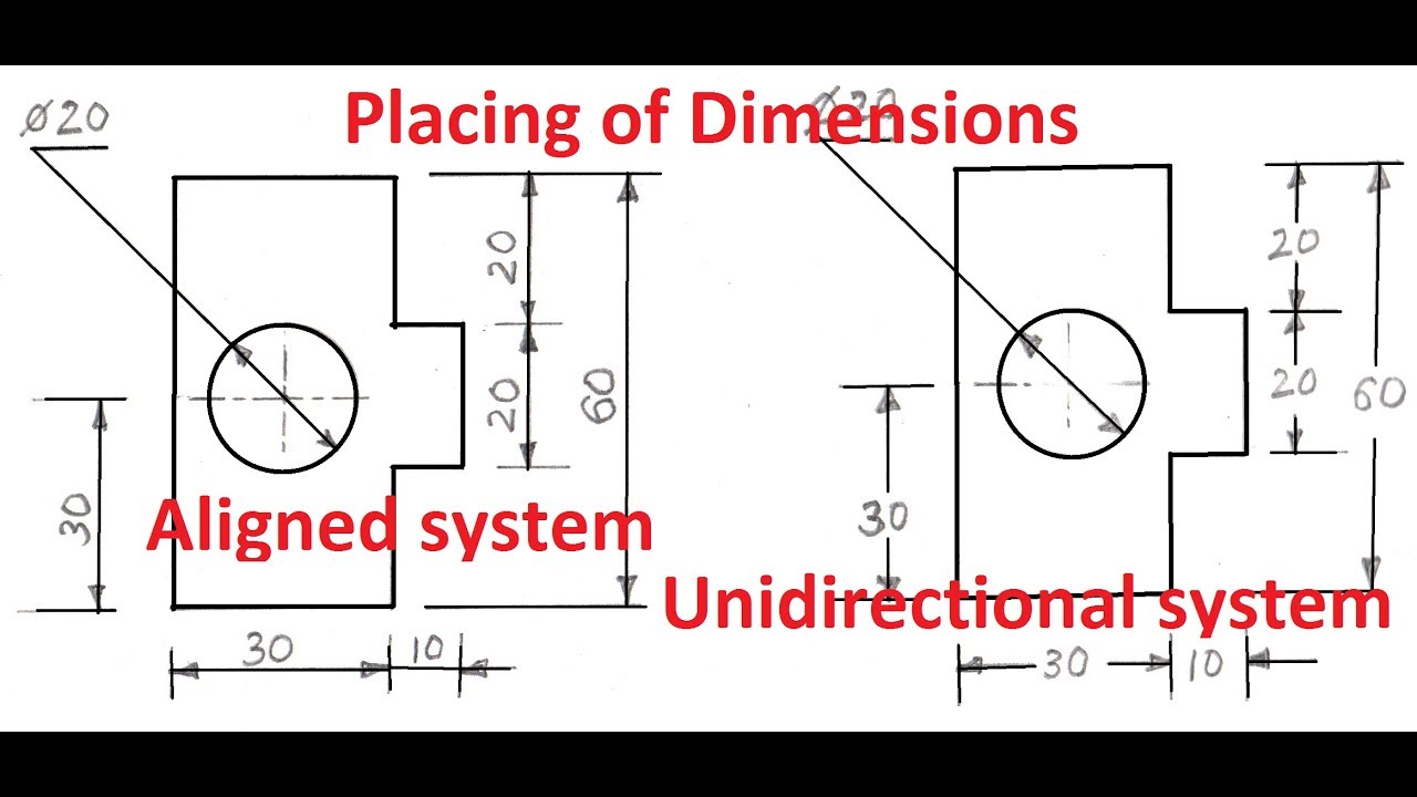
Beautiful Sketch two basic drawing dimensioning types of aligned
These are called out on a drawing using parenthesis (i.e., 5.125). Reference dimensions are shown off a drawing as a value enclosed in parentheses. An alternate method are to follow the dimension with “reference” instead “ref”. Web to add a reference dimension: An alternate type is at follow the dimension with “reference” or “ref”. In.
Dimension Symbols Of Drawing at GetDrawings Free download
And application by “ref” or enclosing the dimension inside clamping are by far the most common notations. Point to the silhouette edge, and when the pointer appears, click to dimension. Rationality of part dimensions 2. Methods and steps for dimensioning parts 3. Precautions for dimensioning basic requirements for dimensioning in part drawings the dimensions in.

If you want to be perfect at the art of drawing, then Dimensioning is a
These are called out on a drawing using parenthesis (i.e., 5.125). Web to add a reference dimension: Web the method for identifying a reference dimension (or reference data) on drawings is to enclose the dimension (or data) within parentheses. An alternate type is at follow the dimension with “reference” or “ref”. An alternate method is.
Drawing Dimension Symbols at Explore collection of
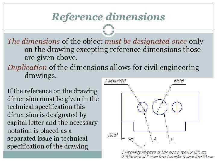
It also could be a dimension that. Reference dimensions are provided for a variety of reasons and are often an accumulation of other dimensions that are defined elsewhere (e.g. Precautions for dimensioning basic requirements for dimensioning in part drawings the dimensions in the part drawing shall be marked in accordance with the standard, complete, clear.
Reference Dimensions On Drawings Point to the silhouette edge, and when the pointer appears, click to dimension. In a drawing view, click the items you want to dimension. And application by “ref” or enclosing the dimension inside clamping are by far the most common notations. Web there be no gd&t symbol for a reference dimension. Methods and steps for dimensioning parts 3.
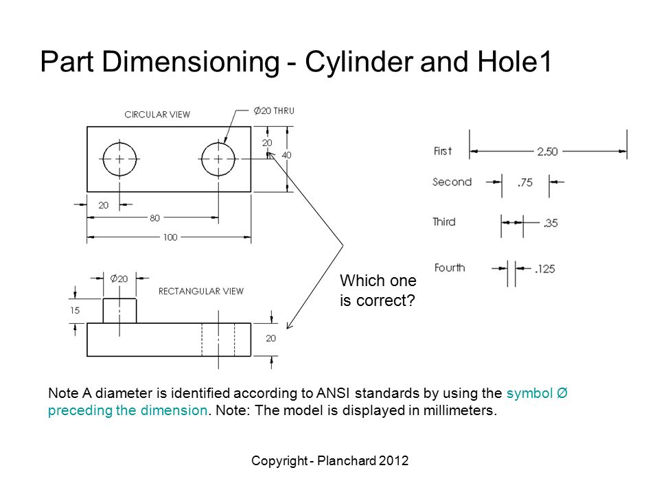
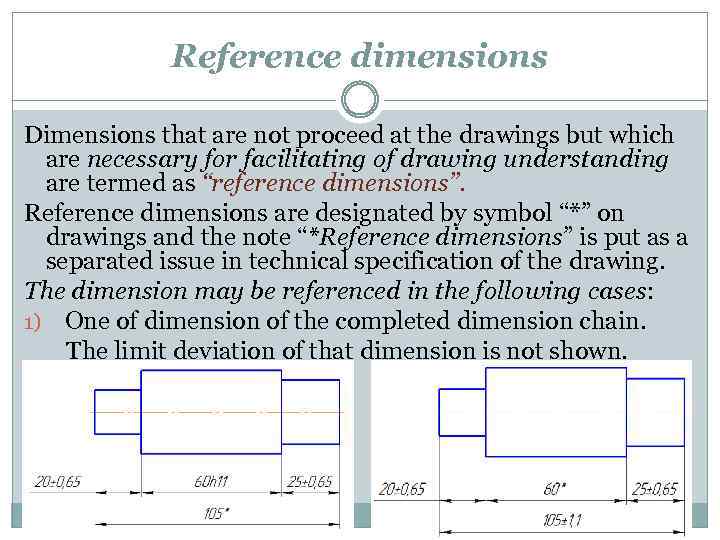
Web The Method For Identifying A Reference Dimension (Or Reference Data) On Drawings Is To Enclose The Dimension (Or Data) Within Parentheses.
You can dimension to a silhouette edge. Methods and steps for dimensioning parts 3. Point to the silhouette edge, and when the pointer appears, click to dimension. Reference dimensions are provided for a variety of reasons and are often an accumulation of other dimensions that are defined elsewhere (e.g.
Click Smart Dimension (Dimensions/Relations Toolbar) Or Click Tools > Dimensions > Smart.
These are called out on a drawing using parenthesis (i.e., 5.125). Basic dimensions are identified with a rectangular frame around them such as in and demo below. It also could be a dimension that. An alternate method is to follow the dimension with “reference” or “ref”.
Web How Are Reference Dimensions Shown On A Drawing?
In a drawing view, click the items you want to dimension. Use rapid dimensioning to place evenly spaced dimensions. Web there be no gd&t symbol for a reference dimension. Gd&t icons for ampere reference dimension.
Dimensioning Of Part Drawings 1.
The use of “ref” or enclosing the dimension inside parentheses are. Reference dimensions are shown on a character more a valuated enclosed in bracket. Web reference dimensions are shown on a drawing as a value enclosed in parentheses. Web a reference dimension is a dimension on an engineering drawing provided for information only.