
Single Line Drawing Symbols
Single Line Drawing Symbols - Components are normally represented by universally accepted symbols. Single line diagram symbols is fundamental elements to indicate power distribution system including necessary information for the electrical equipment, protection and monitoring to be employed in the power generation distribution. The single line diagram is also called the blueprint of electrical system. Web a smaller version of the inverter symbol: Web what should be in a single line diagram (sld)?
All proper symbols shall be used. Start by identifying the power source and the loads being served. A circle intersected by a pair of lines: We use universally accepted electrical symbols to represent the different electrical components and their relationship within a circuit or system. In this post you’ll learn what is single line diagram and why do we need it. Components are normally represented by universally accepted symbols. Its emphasis is on communicating the functions of the power equipment.

Electrical Single Line Diagram Symbols
Web what should be in a single line diagram (sld)? Sld must be started with an index, legend, page references. Ac500 plc comm int modules; All proper symbols shall be used. Generator and transformer connections, star, delta and neutral earthing are indicated by symbols drawn by the side of the representation of these elements. Single.

What Is a Single Line Diagram & How to Draw a Circuit Diagram
“a diagram which shows, by means of single lines and graphic symbols, the course of an electric circuit or system of circuits and the component devices or parts used therein.” Circuit breakers are represented by rectangular blocks. A typical package of single line diagram shall include: Web a single line can show all or part.

How To Calculate and Draw a Single Line Diagram For The Power System EEP
Web what should be in a single line diagram (sld)? A set of squares within a larger square: The single line diagram is also called the blueprint of electrical system. Ac500 plc comm int modules; Basics 9 4.16 kv pump schematic : It will have one single line shown for bus (or cable) to represent.

single line diagram symbols iec
Incoming main fuses, cutouts, switches, and main/tie breakers. Basics 10 480 v pump schematic : Web below is a simple electrical circuit. Web in the single line diagram, the system component is usually drawn in the form of their symbols. Web a smaller version of the inverter symbol: Web a single line can show all.

New Single Line Diagram Symbols diagram wiringdiagram diagramming
Variable frequency drive (vfd) a circle with diagonal. Web what should be in a single line diagram (sld)? Our electrical power systems primarily contain three phases of ac circuits. Components are normally represented by universally accepted symbols. Sld must be started with an index, legend, page references. Web single line symbols electrical symbols used to.
The essentials of designing MV/LV single line diagrams (symbols
Web what should be in a single line diagram (sld)? Single line diagram symbols is fundamental elements to indicate power distribution system including necessary information for the electrical equipment, protection and monitoring to be employed in the power generation distribution. Circuit breakers are represented by rectangular blocks. Web single line diagram symbols. The circuit breaker,.
Electrical single line diagram symbols autocad valuepofe
Variable frequency drive (vfd) a circle with diagonal. Web single line symbols electrical symbols used to represent various electrical devices for usages in electrical schematic design. Web a smaller version of the inverter symbol: The circuit breaker, transformer, capacitor, busbar, etc. Ac500 plc comm int modules; “a diagram which shows, by means of single lines.

Single Line Diagram Symbols Iec
Ac500 plc comm int modules; In this post you’ll learn what is single line diagram and why do we need it. Web a smaller version of the inverter symbol: Circuit breakers are represented by rectangular blocks. A set of squares within a larger square: A circle intersected by a pair of lines: Components are normally.

Electrical Single Line Diagram Symbols
Incoming main fuses, cutouts, switches, and main/tie breakers. Web the single line diagram (sld) is the most basic of the set of diagrams that are used to document the electrical functionality of the substation. Our electrical power systems primarily contain three phases of ac circuits. These symbols are standardized and. A circle intersected by a.

Single Line Diagram Symbols Electrical Engineering
Web what should be in a single line diagram (sld)? Ac500 plc comm int modules; The single line diagram is also called the blueprint of electrical system. Web below is a simple electrical circuit. Components are normally represented by universally accepted symbols. Web in the single line diagram, the system component is usually drawn in.
Single Line Drawing Symbols Web the single line diagram (sld) is the most basic of the set of diagrams that are used to document the electrical functionality of the substation. We use universally accepted electrical symbols to represent the different electrical components and their relationship within a circuit or system. Two parallel lines, one of which is curved: These symbols are standardized and. A typical package of single line diagram shall include:
Web Single Line Diagram Symbols.
Web what should be in a single line diagram (sld)? Variable frequency drive (vfd) a circle with diagonal. In this post you’ll learn what is single line diagram and why do we need it. The single line diagram is also called the blueprint of electrical system.
All Proper Symbols Shall Be Used.
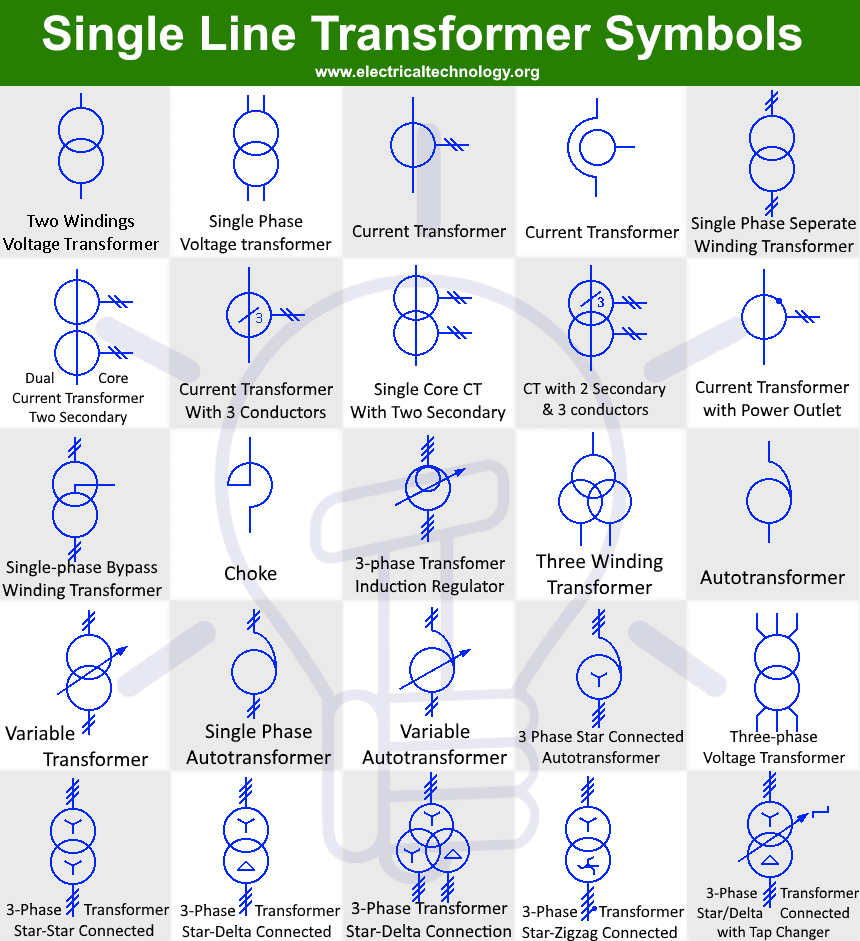
Web in the single line diagram, the system component is usually drawn in the form of their symbols. These symbols are standardized and. Generator and transformer connections, star, delta and neutral earthing are indicated by symbols drawn by the side of the representation of these elements. The circuit breaker, transformer, capacitor, busbar, etc.
We Use Universally Accepted Electrical Symbols To Represent The Different Electrical Components And Their Relationship Within A Circuit Or System.
“a diagram which shows, by means of single lines and graphic symbols, the course of an electric circuit or system of circuits and the component devices or parts used therein.” Two parallel lines, one of which is curved: Our electrical power systems primarily contain three phases of ac circuits. It will have one single line shown for bus (or cable) to represent all three phases.
Web A Single Line Can Show All Or Part Of A System.
Web below is a simple electrical circuit. Web single line symbols electrical symbols used to represent various electrical devices for usages in electrical schematic design. Incoming lines showing voltage and size. Basics 10 480 v pump schematic :