
Symbols In Mechanical Drawing
Symbols In Mechanical Drawing - Web the drawing abbreviations and symbols of mechanical design and engineering save 0 you may easily identify the abbreviation kg and cm, do you know the meaning of cyl and equi sp on a cnc design? The bis recommended symbols for indicating the surface finish are shown in table a. In the context of cnc (computer numerical control) design, the abbreviations “cyl” and “equi sp” typically refer to specific features or parameters. For the roughness values greater than 25μm, the symbol is used. Completed symbols are usable in standard.
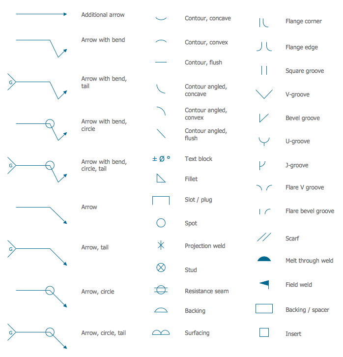
Web the vector stencils library dimensioning and tolerancing contains 45 symbols of geometric dimensions and mechanical tolerances, geometric symbols, callouts, and text boxes and inserts. It is more than simply a drawing, it is a graphical language that communicates ideas and information. True position theory (size value in rectangular frame) classification and symbols of geometric tolerance characteristics the following is a list of symbols used for geometric tolerancing. Options for welding symbols are: Web some commonly used dimensioning symbols include: On the bottom of the title block, the mechanical engineering drawing provides other information that tells you more about the cap. You can also check out the gd&t symbols and terms on our site.

Engineering Drawing Symbols And Their Meanings Pdf at PaintingValley
Unlike a model, engineering drawings offer more specific detail and requirements, such as: You can even flip between scales on the fly. Completed symbols are usable in standard. Web it is suggested to indicate the surface roughness on drawing by symbols. Use these geometric dimensioning and tolerancing (gd&t) shapes to create annotated mechanical drawings. The.

Piping Coordination System Mechanical symbols for Isometric drawings
Use the welding.dwg file in the autocad samples folder: Web it is suggested to indicate the surface roughness on drawing by symbols. Web common blueprint symbols. Dimensioning and tolerancing with 45 elements; Web a convenient guide for geometric dimensioning and tolerancing (gd&t) symbols at your fingertips. Web the drawing abbreviations and symbols of mechanical design.

Mechanical Engineering Symbols Cadbull
Web currently, we have 16 symbols for geometric tolerances, which are categorized according to the tolerance they specify. This makes understanding the drawings simple with little to no personal. Need to know for dispelling uncertainty in drawings. Web basic types of symbols used in engineering drawings are countersink, counterbore, spotface, depth, radius, and diameter. Web.
Mechanical Engineering Solution
The bis recommended symbols for indicating the surface finish are shown in table a. Web some commonly used dimensioning symbols include: You can also check out the gd&t symbols and terms on our site. An engineering (or technical) drawingis a graphical representation of a part, assembly, system, or structure and it can be produced using.

Mechanical Drawing Symbols
True position theory (size value in rectangular frame) classification and symbols of geometric tolerance characteristics the following is a list of symbols used for geometric tolerancing. This symbol is used to denote the diameter of a circle or cylindrical feature. Use these geometric dimensioning and tolerancing (gd&t) shapes to create annotated mechanical drawings. Web it.

Basic Engineering Practice Machine Design & Materials PE Exam Tools
Smartdraw works in both us/imperial and metric standards of measure and also allows you to customize the scale of your mechanical drawing. Web basic and common symbols. On the bottom of the title block, the mechanical engineering drawing provides other information that tells you more about the cap. Options for welding symbols are: The bis.

Mechanical Engineering Symbols And Their Meanings
Web the drawing abbreviations and symbols of mechanical design and engineering save 0 you may easily identify the abbreviation kg and cm, do you know the meaning of cyl and equi sp on a cnc design? Web it is suggested to indicate the surface roughness on drawing by symbols. Click on the links below to.

Mechanical Engineering Drawing Symbols Pdf Free Download at
Symbols used in gd&t callouts. Web where to find or options to create welding symbols in autocad. Use these geometric dimensioning and tolerancing (gd&t) shapes to create annotated mechanical drawings. This makes understanding the drawings simple with little to no personal. Smartdraw works in both us/imperial and metric standards of measure and also allows you.

Mechanical Engineering Drawing Symbols Pdf Free Download at
Use these geometric dimensioning and tolerancing (gd&t) shapes to create annotated mechanical drawings. Radius symbol (r or ⌀ with a diagonal line through it): Web engineering drawings (aka blueprints, prints, drawings, mechanical drawings) are a rich and specific outline that shows all the information and requirements needed to manufacture an item or product. We offer.

Design Elements Dimensioning and Tolerancing Mechanical design
Web graphics communications are used in every phase of engineering design starting from concept illustration all the way to the manufacturing phase. An engineering (or technical) drawingis a graphical representation of a part, assembly, system, or structure and it can be produced using freehand, mechanical tools, or computer methods. Smartdraw works in both us/imperial and.
Symbols In Mechanical Drawing In the context of cnc (computer numerical control) design, the abbreviations “cyl” and “equi sp” typically refer to specific features or parameters. Web basic and common symbols. The following is a short list of symbols that normally appear on a technical drawing and need understanding. Mechanical drawing symbols — fluid power equipment library mechanical engineering solution offers 602 commonly used mechanical drawing symbols and objects which are professionally designed and grouped in 8 libraries: You can also check out the gd&t symbols and terms on our site.
Completed Symbols Are Usable In Standard.
They are used to help engineers and architects communicate with each other about the design of various objects. Web some commonly used dimensioning symbols include: Web engineering drawing basics explained. Dimensioning and tolerancing with 45 elements;
Web The Vector Stencils Library Dimensioning And Tolerancing Contains 45 Symbols Of Geometric Dimensions And Mechanical Tolerances, Geometric Symbols, Callouts, And Text Boxes And Inserts.
Smartdraw works in both us/imperial and metric standards of measure and also allows you to customize the scale of your mechanical drawing. Use the welding.dwg file in the autocad samples folder: Technical standards are the definition and glossary of abbreviations, symbols, and acronyms that may be found on engineering drawings. The symbols covered in on the following pages are an example of the widespread use of symbols and abbreviations in industry.
Symbols Used In Gd&T Callouts.
Web mechanical engineering solution — 8 libraries are available with 602 commonly used mechanical drawing symbols in mechanical engineering solution, including libraries called bearings with 59 elements of roller and ball bearings, shafts, gears, hooks, springs, spindles and keys; Web basic types of symbols used in engineering drawings are countersink, counterbore, spotface, depth, radius, and diameter. Need to know for dispelling uncertainty in drawings. Web graphics communications are used in every phase of engineering design starting from concept illustration all the way to the manufacturing phase.
You Can Also Check Out The Gd&T Symbols And Terms On Our Site.
Web it is suggested to indicate the surface roughness on drawing by symbols. In the context of cnc (computer numerical control) design, the abbreviations “cyl” and “equi sp” typically refer to specific features or parameters. There are dozens of different symbols that can be used, but most share a few common elements. Options for welding symbols are: