
Valve Drawing Symbols
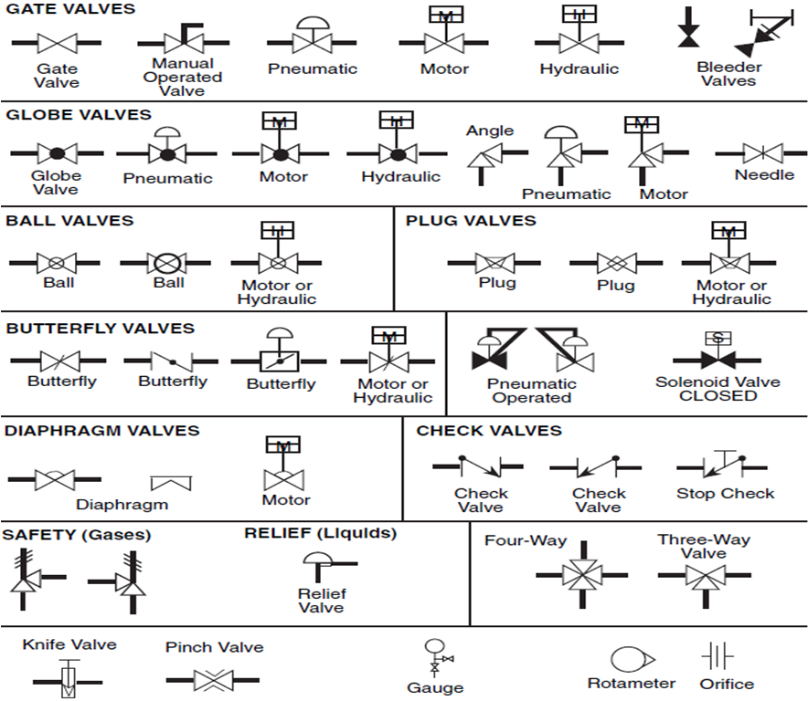
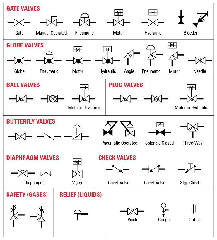
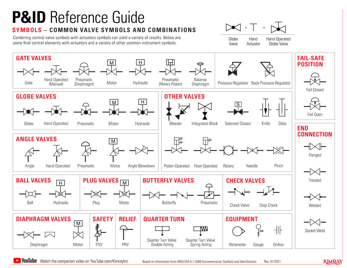
Valve Drawing Symbols - The pipe lines are represented by lines connecting to each side of the valve symbol. A gate valve with the direction of flow running from left to right. Web three symbols shown below are the gate valve symbols used in isometric drawings. So, to understand a system shown on a process flow diagram (fd) or a piping and instrument diagram (p&id), you must understand the valve symbols. • examples of the common types are the globe valve, gate valve, ball valve, plug valve, butterfly valve, diaphragm valve, check valve, pinch valve, and safety valve.
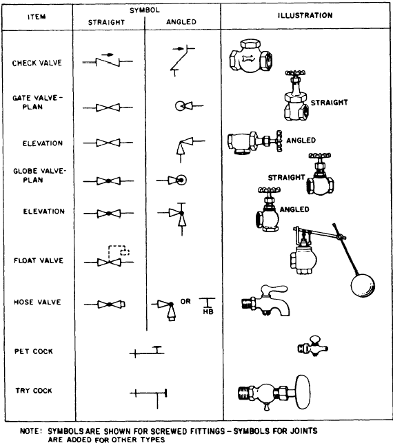
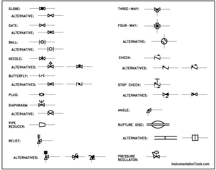
A gate valve with the direction of flow running from left to right. Various types of lines are used to represent different pipes, tubes, and hoses. Figure 1 shows the symbols that depict the major valve types. Be consistent with the symbols throughout the drawing so that the p&id diagram can be easily comprehended by everyone who works with it. It should be noted that globe and gate valves will often be depicted by the same valve symbol. Web valve symbols valves are used to control the direction, flow rate, and pressure of fluids. The pipe lines are represented by lines connecting to each side of the valve symbol.
Valve Sign Symbols The Engineering Concepts
Examples of these symbols can be found further down in this article. General instrument or function symbols. Instruments can have various locations, accessibilities, and functionalities in the field for certain processes. So, to understand a system shown on a process flow diagram (fd) or a piping and instrument diagram (p&id), you must understand the valve.

Valve Symbols in P&ID Ball Valve, Relief Valve and more
Instruments can have various locations, accessibilities, and functionalities in the field for certain processes. Web environments in which valves must operate, a vast array of valve types have been developed. Various types of lines are used to represent different pipes, tubes, and hoses. Figure 1 shows the symbols that depict the major valve types. These.
What symbols to use for valves
These illustrations, commonly referred to as piping and instrumentation diagram (p&di) symbols, may vary slightly between organizations but similar sketches are used to identify types and position of valves. So, to understand a system shown on a process flow diagram (fd) or a piping and instrument diagram (p&id), you must understand the valve symbols. Be.
Valve Symbols in P&ID Ball Valve, Relief Valve and more
The valve symbols can show you the type, how they operate, and more. Web valve symbols are used to signify the pressure, flow and direction of fluids through a valve. Web valve symbols valves are used to control the direction, flow rate, and pressure of fluids. Web this article discusses the main symbols of ball.

Drawing Symbol for Valves and Joints Engineer Diary
General instrument or function symbols. Each p&id has its own legend that identifies the symbols for the various equipment. Web this article discusses the main symbols of ball valves used in a p&id with a typical example. While there is some variation, examples of the standard symbols for control valves are in the pdf below..
Valve symbols
It is important to describe this clearly in a p&id. Each p&id has its own legend that identifies the symbols for the various equipment. Various types of lines are used to represent different pipes, tubes, and hoses. General instrument or function symbols. Web three symbols shown below are the gate valve symbols used in isometric.

Types Of Valves, Their Functions And Symbols Engineering Discoveries
• examples of the common types are the globe valve, gate valve, ball valve, plug valve, butterfly valve, diaphragm valve, check valve, pinch valve, and safety valve. You can see that p&id and isometric. Web three symbols shown below are the gate valve symbols used in isometric drawings. Web valve symbols for p&ids. A valve.
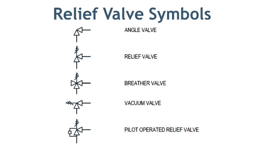
The Most Common Control Valve Symbols on a P&ID Kimray
• each type of valve has been designed to meet specific needs. The pipe lines are represented by lines connecting to each side of the valve symbol. Various types of lines are used to represent different pipes, tubes, and hoses. You can see that p&id and isometric. A valve controls the flow of air or.
The Most Common Control Valve Symbols on a P&ID Kimray
A gate valve with the direction of flow running from left to right. So, to understand a system shown on a process flow diagram (fd) or a piping and instrument diagram (p&id), you must understand the valve symbols. For a globe valve, a symbol is modified by adding a small dark circle between triangles. While.
Piping and Instrumentation Symbols Instrumentation Tools
These illustrations, commonly referred to as piping and instrumentation diagram (p&di) symbols, may vary slightly between organizations but similar sketches are used to identify types and position of valves. Instruments can have various locations, accessibilities, and functionalities in the field for certain processes. Be consistent with the symbols throughout the drawing so that the p&id.
Valve Drawing Symbols The valve symbols can show you the type, how they operate, and more. It is important to describe this clearly in a p&id. So, to understand a system shown on a process flow diagram (fd) or a piping and instrument diagram (p&id), you must understand the valve symbols. You can see that p&id and isometric. Web this article discusses the main symbols of ball valves used in a p&id with a typical example.
Web Environments In Which Valves Must Operate, A Vast Array Of Valve Types Have Been Developed.
Web valve symbols for p&ids. Below is a table of these symbols commonly used in p&ids. While there is some variation, examples of the standard symbols for control valves are in the pdf below. Web three symbols shown below are the gate valve symbols used in isometric drawings.
These Illustrations, Commonly Referred To As Piping And Instrumentation Diagram (P&Di) Symbols, May Vary Slightly Between Organizations But Similar Sketches Are Used To Identify Types And Position Of Valves.
The pipe lines are represented by lines connecting to each side of the valve symbol. General instrument or function symbols. So, to understand a system shown on a process flow diagram (fd) or a piping and instrument diagram (p&id), you must understand the valve symbols. A gate valve with the direction of flow running from left to right.
A Valve Controls The Flow Of Air Or Liquid Through The Piping.
• examples of the common types are the globe valve, gate valve, ball valve, plug valve, butterfly valve, diaphragm valve, check valve, pinch valve, and safety valve. • each type of valve has been designed to meet specific needs. For a globe valve, a symbol is modified by adding a small dark circle between triangles. A p&id for a heat exchange process.
It Is Important To Describe This Clearly In A P&Id.
Each p&id has its own legend that identifies the symbols for the various equipment. Web the control valve symbols on a p&id differ depending on the type of valve specified for the application. Figure 1 shows the symbols that depict the major valve types. Be consistent with the symbols throughout the drawing so that the p&id diagram can be easily comprehended by everyone who works with it.