
Draw The Shear Diagram For The Beam
Draw The Shear Diagram For The Beam - Web draw the shear force and bending moment diagrams for the beam shown in the figure, when dimensions and loadings of the beam get values a=1.0 m,b=1 m,c=3.2 m,d=0.8 m,f=16 kn,p=12 kn and q=23kn//m. You'll get a detailed solution from a subject matter expert that helps you learn core concepts. Lined up below the free body diagram, draw a set. In this case we have come to a negative 20kn force, so we will minus 20kn from the existing 10kn. This problem has been solved!
Keep moving across the beam, stopping at every load that acts on the beam. Click on add discontinuity to add discontinuity lines. Web draw the shear and moment diagrams for the compound beam. The vertical support reaction at a on. Lined up below the free body diagram, draw a set. Leave all distributed forces as distributed forces and do not replace them with the equivalent point load. Label all significant points on each diagram.
Solved Draw the shear and moment diagrams for the beam.
For the beam structure shown in this figure draw the shear and. In a simply supported beam, the only vertical force is the 5kn/m force, which when multiplied by the length of the member (l = 10) we get 5*10 = 50 kn. Web learn to draw shear force and moment diagrams using 2 methods,.

Draw The Shear Diagram For The Beam Set P 800 Lb A 5 Ft L 12 Ft
This page will walk you through what shear forces and bending moments are, why they are useful, the procedure for drawing the diagrams and some other keys aspects as well. Click on add discontinuity to add discontinuity lines. Shear and moment diagrams and formulas are excerpted from the western woods use book, 4th edition, and.

Ultimate Guide to Shear Force and Bending Moment Diagrams
This page will walk you through what shear forces and bending moments are, why they are useful, the procedure for drawing the diagrams and some other keys aspects as well. You'll get a detailed solution from a subject matter expert that helps you learn core concepts. Solve for all external forces acting on the body..
Solved Draw the shear and moment diagrams for the beam.
Web draw the shear and moment diagrams for the beam. You will have a robust system of analysis that allows you to confidently tackle the analysis of. To create the shear force diagram, we will use the following process. Web learn to draw shear force and moment diagrams using 2 methods, step by step. Draw.
Solved Draw the shear diagram for the beam. Follow the
Write shear and moment equations for the beams in the following problems. Lined up below the free body diagram, draw a set. In general the process goes like this:1) calcul. Set m0 = 500 n?m, l = 8 m. Leave all distributed forces as distributed forces and do not replace them with the equivalent point.
Solved Draw the shear diagram for the beam. Follow
For the beam structure shown in this figure draw the shear and bendingmoment diagrams. Web learn to draw shear force and moment diagrams using 2 methods, step by step. Draw the shear and moment diagrams for the beam. You'll get a detailed solution from a subject matter expert that helps you learn core concepts. We.

Solved Draw the shear and moment diagrams for the beam
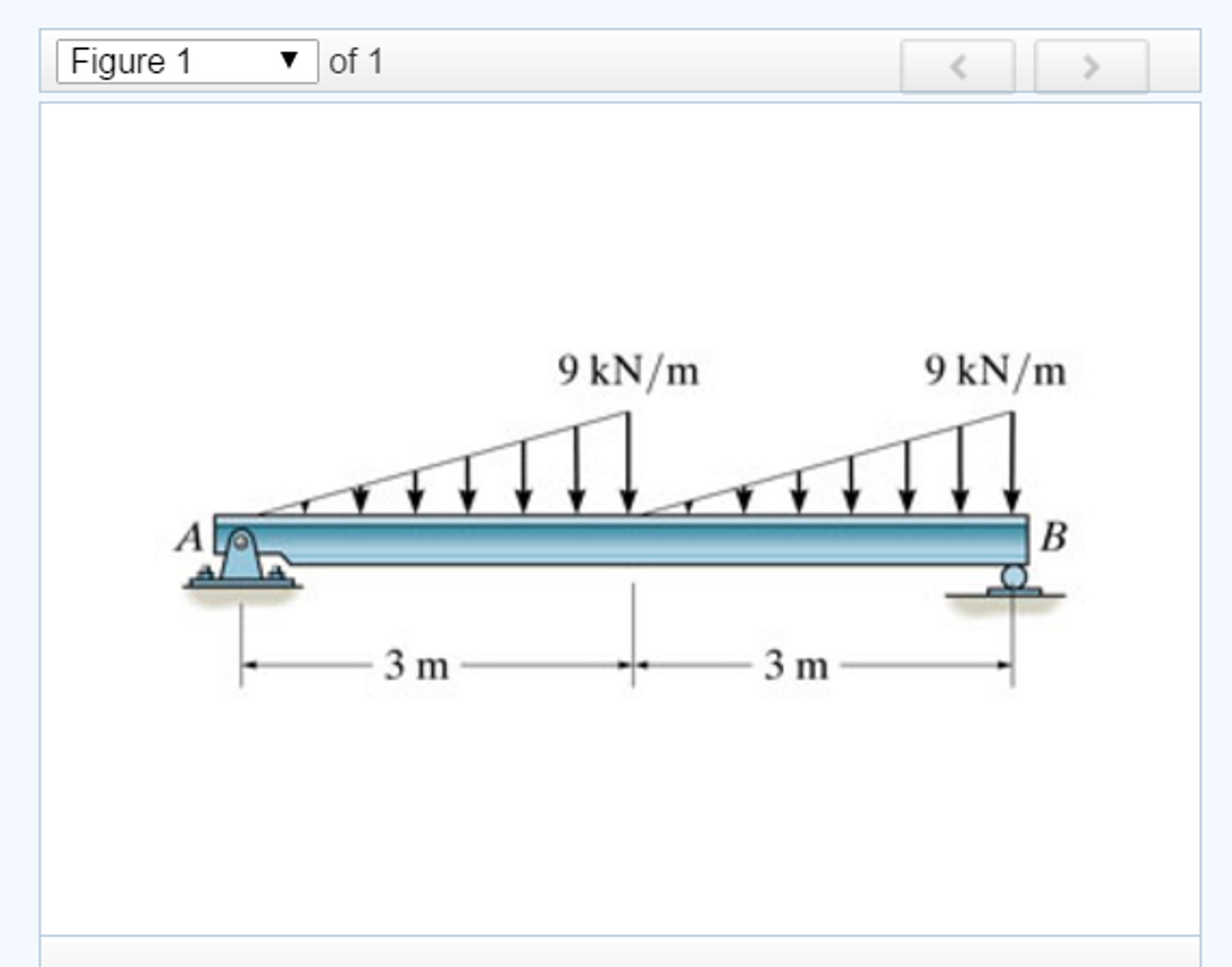
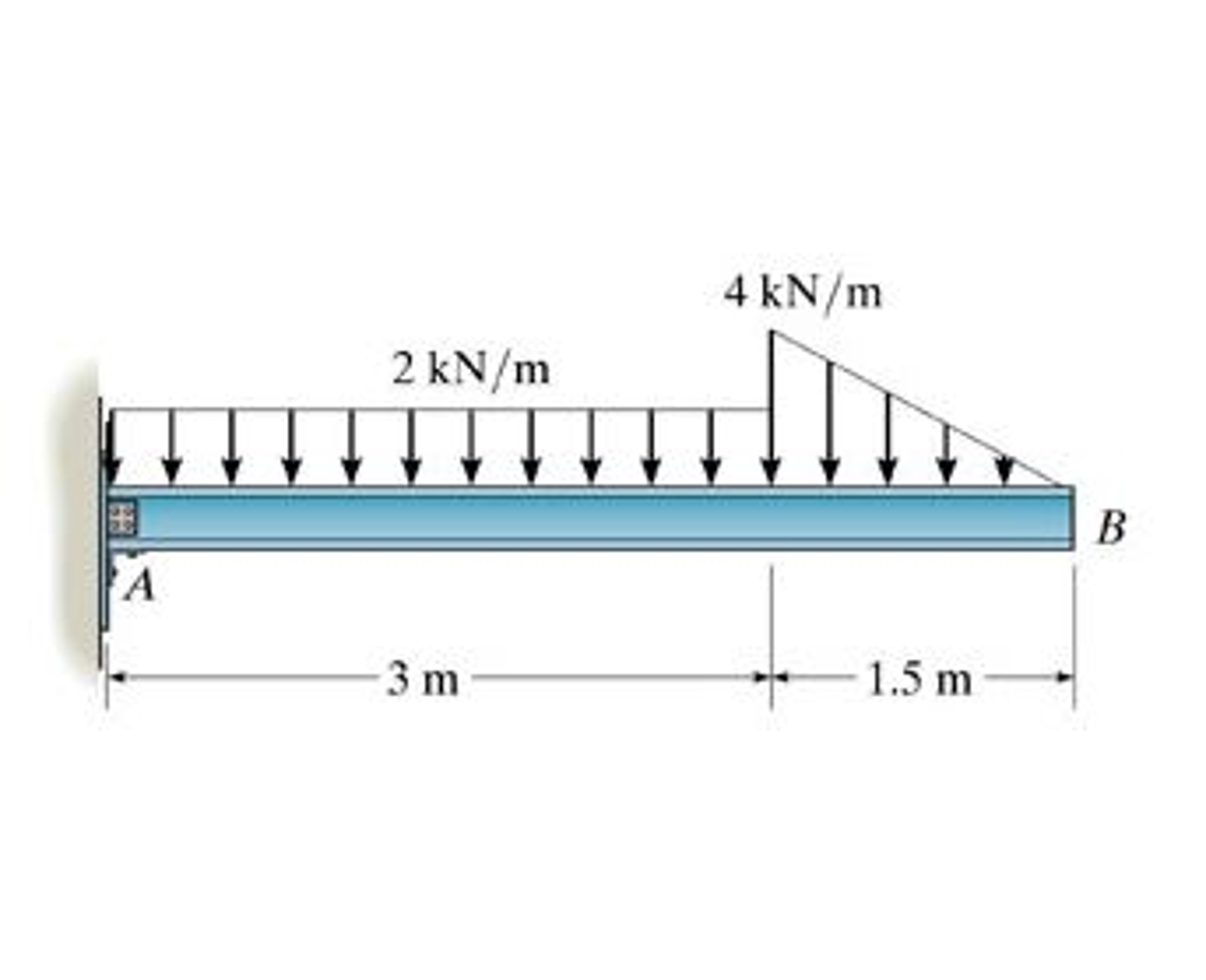
Draw the moment diagram for the beam. This problem has been solved! Draw the shear and moment diagrams for the beam. Web this video explain how to draw shear force and bending moment diagram of a beam with a triangular distributed load acting on the beam. You'll get a detailed solution from a subject matter.

Solved Draw the shear and moment diagrams for the beam.
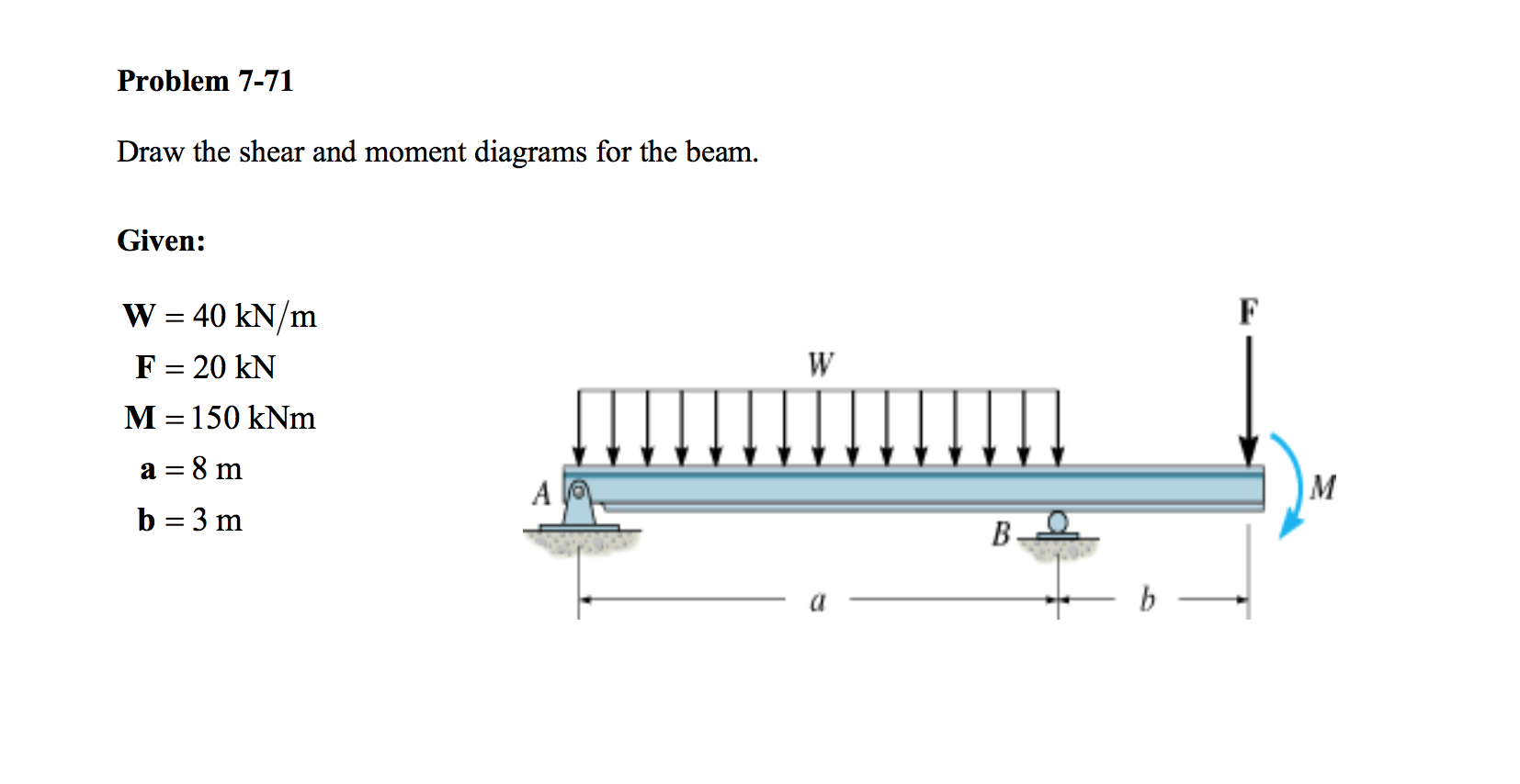
20 kn 40 kn/m cl 150 kn m 8 m 3 m prob. Web drawing the shear diagram. Web draw the shear force and bending moment diagrams for the beam shown in the figure, when dimensions and loadings of the beam get values a=1.0 m,b=1 m,c=3.2 m,d=0.8 m,f=16 kn,p=12 kn and q=23kn//m. Web here are.

Learn How To Draw Shear Force And Bending Moment Diagrams Engineering
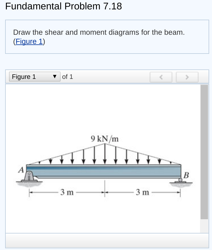
Solve for all external forces acting on the body. Draw a horizontal line to represent the beam and divide the line by putting points at the following locations: Neglect the mass of the beam in each problem. Me 13 fundamental problem 7.13 fundamental problem 7.13 draw the shear and moment diagrams for the beam. Web.

Solved Draw the shear and moment diagrams for the beam, and
Also, draw shear and moment diagrams, specifying values at all change of loading positions and at points of zero shear. Leave all distributed forces as distributed forces and do not replace them with the equivalent point load. Draw the moment diagram for the beam. Let a = 5.0 ft, b = 4.5 ft, p =.
Draw The Shear Diagram For The Beam Web draw the shear and moment diagrams for the beam. Draw out a free body diagram of the body horizontally. Web here are simple five steps applicable for drawing almost all types of shear force diagram correctly (refer the following typical example in connection with the below steps): In each problem, let x be the distance measured from left end of the beam. Web this is an example problem that will show you how to graphically draw a shear and moment diagram for a beam.
When You Get To A Load, Add To The Shear Force Diagram By The Amount Of The Force.
The shear force diagram is drawn first before the bending. Keep moving across the beam, stopping at every load that acts on the beam. Draw the shear and moment diagrams for the beam. Me 13 fundamental problem 7.13 fundamental problem 7.13 draw the shear and moment diagrams for the beam.
To Create The Shear Force Diagram, We Will Use The Following Process.
Let a = 5.0 ft, b = 4.5 ft, p = 21 kips, and w = 3.0 kips/ft. Draw a horizontal line to represent the beam and divide the line by putting points at the following locations: Solve for all external forces acting on the body. Set m0 = 500 n?m, l = 8 m.
Shear And Moment Diagrams And Formulas Are Excerpted From The Western Woods Use Book, 4Th Edition, And Are Provided Herein As A Courtesy Of Western Wood Products Association.
The vertical support reaction at a on. Neglect the mass of the beam in each problem. Web the first step in calculating these quantities and their spatial variation consists of constructing shear and bending moment diagrams, \(v(x)\) and \(m(x)\), which are the internal shearing forces and bending moments induced in. (see above) sum up the forces in the vertical direction.
In General The Process Goes Like This:1) Calcul.
Web draw the shear force and bending moment diagrams for the beam shown in the figure, when dimensions and loadings of the beam get values a=1.0 m,b=1 m,c=3.2 m,d=0.8 m,f=16 kn,p=12 kn and q=23kn//m. Draw the shear and moment diagrams for the beam. Figure 1 of 1 8 kn 6 kn 4 kn 1 m 1 m e previous l 4 of 4 l return to ass part a draw the shear diagram for the beam. For the beam structure shown in this figure draw the shear and bendingmoment diagrams.